Honda Ridgeline. Manual - part 476
*01
SJC8A00J32323300000EAAT00
−
−
−
−
−
−
22-200
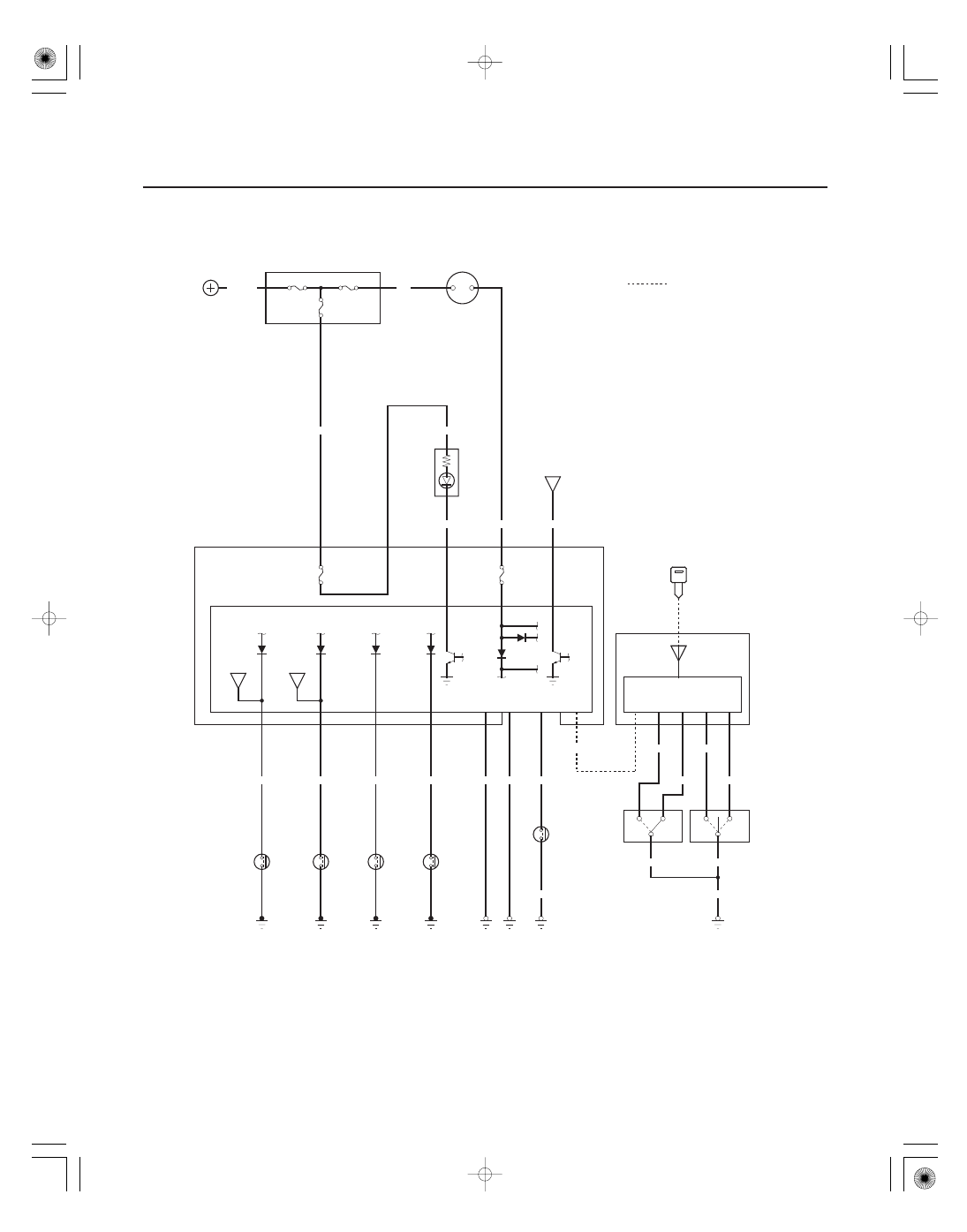
Entry Lights Control System
Circuit Diagram
1
1
1
1
LT GRN/RED
GRN/YEL
H12
E14
BLU/RED
W4
BLK/YEL
BATTERY
No.22 (BAT) (120 A)
UNDER HOOD FUSE/RELAY BOX
No.15
(40 A)
No.23 (IG) (50 A)
WHT
IGNITION SWITCH
IG1
BAT
WHT/BLK
5
6
P7
E15
GRN
G401
1
2
MICU
UNDER DASH FUSE/RELAY BOX
WHT/RED
(7.5 A)
No.7
No.21
(7.5 A)
YEL
BLK/YEL
BLK
E9
G501
G403
P1
BLK
RED/WHT
P13
H13
BLK
B CAN
B CAN
BRN/BLK
J4
16
7
WHT/BLK
YEL/RED
22
8
WHT/RED
WHT
21
LOCK
LOCK
BLK
BLK
BLK
G401
: Communication line
GRN/WHT
1
2
1
3
2
3
X35
B4
A6
G1
D6
DRIVER’S
DOOR KEY
CYLINDER
SWITCH
DRIVER’S
DOOR LOCK
KNOB
SWITCH
UN
LOCK
UN
LOCK
POWER WINDOW
MASTER SWITCH
KEYLESS
TRANSMITTER
KEYLESS
RECEIVER
ANTENNA
DOOR MULTIPLEX
CONTROL UNIT
IGNITION
KEY
SWITCH
(Closed :
Key inserted)
DRIVER’S
DOOR
SWITCH
(Closed :
Door open)
DRIVER’S
DOOR
COURTESY
LIGHT
FRONT
PASENGER’S
DOOR
COURTESY
LIGHT
IGNITION
KEY LIGHT
(LED)
IG1 HOT in ON (II) and
START (III)
INTERIOR
LIGHTS
SWITCH
RIGHT
REAR DOOR
SWITCH
(Closed :
Door open)
LEFT
REAR DOOR
SWITCH
(Closed :
Door open)
FRONT
PASSENGER’S
DOOR
SWITCH
(Closed :
Door open)