Honda Ridgeline. Manual - part 453
SJC8A00K763000Y1000FAAT10
−
−
−
−
−
−
DTC B1000:
YES
NO
YES
NO
Control Unit
Connector
YES
NO
Control Unit
Appropriate Connector
22-108
Multiplex Integrated Control System
DTC Troubleshooting
Communication Bus Line Error
(BUS-OFF)
1. Clear the DTCs with the HDS.
2. Turn the ignition switch OFF, and then back ON (II).
3. Wait for 6 seconds or more.
4. Check for DTCs with the HDS.
Go to step 5.
Intermittent failure. The communication bus
line is OK at this time. Check for loose or poor
connections, or worn/shorted wires. If the
connections are good, check the battery condition
(see page 22-74) and the charging system.
5. Check for DTCs with the HDS.
Go to step 6.
Faulty MICU; replace the under-dash fuse/
relay box.
6. Turn the ignition switch OFF.
7. Disconnect the appropriate connector at each
control unit in the table one at a time. Clear the DTC,
then recheck for DTCs after each unit is
disconnected.
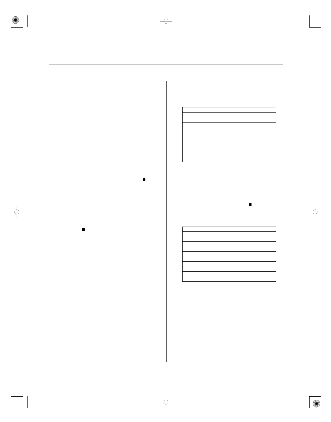
Gauge Control
Module
Connector B (14P)
Relay Control
Module
Connector J (10P)
Door Multiplex
Control Unit
Power window master
switch connector (23P)
Combination Switch
Control Unit
Connector (12P)
HVAC Control Unit/
Climate Control Unit
Connector (30P)
Go to step 8.
Check the power and grounds to the control
unit that was disconnected when B1000 did not
reset. If OK, replace the control unit.
8. Disconnect all of the appropriate connectors for
each of the units in the table.
Gauge Control
Module
Connector B (14P)
Relay Control
Module
Connector J (10P)
Door Multiplex
Control Unit
Power window master
switch connector (23P)
Combination Switch
Control Unit
Connector (12P)
HVAC Control Unit/
Climate Control Unit
Connector (30P)
9. Disconnect under-dash fuse/relay box connectors
D (17P), J (21P), N (45P), X (39P), and P (30P).
Is DT C B1000 indicated?
Ar e DT Cs B1005, B1006, B1007 , B1008, B1010,
and B1011 also indicated?
Is DT C B1000 indicated with each individual unit
disconnected?