Honda Ridgeline. Manual - part 427


  Index      Honda     Honda Ridgeline - service repair manual 2006-2008 year


Search            


Content   ..  425  426  427  428   ..


Honda Ridgeline. Manual - part 427


05

06

07

08

10

Handling Wires and Harnesses

22-4

Body Electrical

General Troubleshooting Information (cont’d)

A

B

A

(P/N 08798-9001)

DOWN

A

A

B

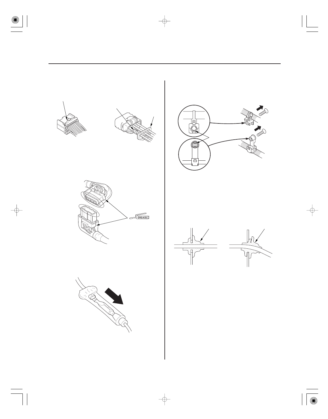
• Check for loose retainer (A) and rubber seals (B).

• The backs of some connectors are packed with

dielectric grease. Add grease if necessary. If the
grease is contaminated, replace it.

• Insert the connector all the way and make sure it is

securely locked.

• Position wires so that the open end of the cover faces

down.

• Secure wires and wire harnesses to the frame with

their respective wire ties at the designated locations.

• Remove clips carefully; don’t damage their locks (A).

• After installing harness clips, make sure the harness

doesn’t interfere with any moving parts.

• Keep wire harnesses away from exhaust components

and other hot parts, from sharp edges of brackets and
holes, and from exposed screws and bolts.

• Seat grommets in their grooves properly (A). Do not

leave grommets distorted (B).

11

12

Testing and Repairs

Five-step Troubleshooting

22-5

• Do not use wires or harnesses with broken insulation.

Replace them or repair them by wrapping the break
with electrical tape.

• Never attempt to modify, splice, or repair SRS wiring.

If there is an open or damage is SRS wiring or
terminals, replace the harness.

• After installing parts, make sure that no wires are

pinched under them.

• When using electrical test equipment, follow the

manufacturer’s instructions and those described in
this manual.

• If possible, insert the probe of the tester from the wire

side (except waterproof connector).

• Use back probe adaptor 07TAZ-001020A.

• Refer to the instructions in the Honda Terminal Kit for

identification and replacement of connector terminals.

1. Verify The Complaint:

Turn on all the components in the problem circuit
to verify the customer complaint. Note the
symptoms. Do not begin disassembly or testing
until you have narrowed down the problem area.

2. Analyze The Schematic:

Look up the schematic for the problem circuit.
Determine how the circuit is supposed to work by
tracing the current paths from the power feed
through the circuit components to ground. If
several circuits fail at the same time, the fuse or a
ground is a likely cause.

Based on the symptoms and your understanding of
the circuit operation, identify one or more possible
causes of the problem.

3. Isolate The Problem By Testing The Circuit:

Make circuit tests to check the diagnosis you made
in step 2. Keep in mind that a logical, simple
procedure is the key to efficient troubleshooting.
Test for the most likely cause of failure first. Try to
make tests at points that are easily accessible.

4. Fix The Problem:

Once the specific problem is identified, make the
repair. Be sure to use proper tools and safe
procedures.

5. Make Sure The Circuit Works:

Turn on all components in the repaired circuit in all
modes to make sure you’ve fixed the entire
problem. If the problem was a blown fuse, be sure
to test all of the circuits on the fuse. Make sure no
new problems turn up and the original problem
does not recur.

(cont’d)

01

14

Wire Color Codes

How to Check for DTCs with the Honda
Diagnostic System (HDS)

22-6

Body Electrical

General Troubleshooting Information (cont’d)

WHT/BLK

A

The following abbreviations are used to identify wire
colors in the circuit schematics:

...................................

.....................................
.....................................

....................................
....................................
....................................
....................................
....................................
....................................
....................................
....................................

...............................

..............................

WHT

.

White

YEL

.

Yellow

BLK

.

Black

BLU

.

Blue

GRN

.

Green

RED

.

Red

ORN

.

Orange

PNK

.

Pink

BRN

.

Brown

GRY

.

Gray

PUR

.

Purple

LT BLU

.

Light Blue

LT GRN

.

Light Green

The wire insulation has one color or one color with
another color stripe. The second color is the stripe.

NOTE: For specific operations, refer to the user’s
manual that came with the Honda Diagnostic System
(HDS).

1. Connect the HDS to the Data Link Connector (DLC)

(A) located under the driver’s side of the dashboard.

2. Turn the ignition switch ON (II).

3. Make sure the HDS communicates with the vehicle.

If it doesn’t, troubleshoot the DLC circuit (see page
11-194).

4. Enter BODY ELECTRICAL, then select the TEST

MODE menu.

5. Check for DTCs with the HDS.

6. If any DTCs are indicated, note them, and go to the

indicated DTC troubleshooting.

01

SJC8A00J54200000000DEAT01

22-7

Relay and Control Unit Locations

Engine Compartment

SEAT HEATER RELAY

UNDER-HOOD
FUSE/RELAY BOX

ETCS RELAY

HEATED WINDSHIELD
WIPER AREA RELAY

A/C COMPRESSOR
CLUTCH RELAY

BLOWER MOTOR RELAY

RELAY CONTROL MODULE
(Built into the under-hood
fuse/relay box)

FAN CONTROL RELAY

RADIATOR FAN RELAY

A/C CONDENSER FAN RELAY

AUXILIARY UNDER-HOOD
RELAY BOX

PCM

AUXILIARY UNDER-HOOD
FUSE BOX

VSA MODULATOR-CONTROL UNIT

Wire colors: GRN, BLU/BLK,
BLU/YEL, BLK and WHT/RED

Wire colors: YEL, BLU/BLK,
YEL and GRN

Wire colors: GRN/YEL, BLU/YEL,
BLU/YEL and YEL/GRN


Content   ..  425  426  427  428   ..