Honda Ridgeline. Manual - part 421
*01
*02
−
−
−
−
−
−
YES
NO
YES
NO
YES
NO
21-120
Climate Control
DTC Troubleshooting (cont’d)
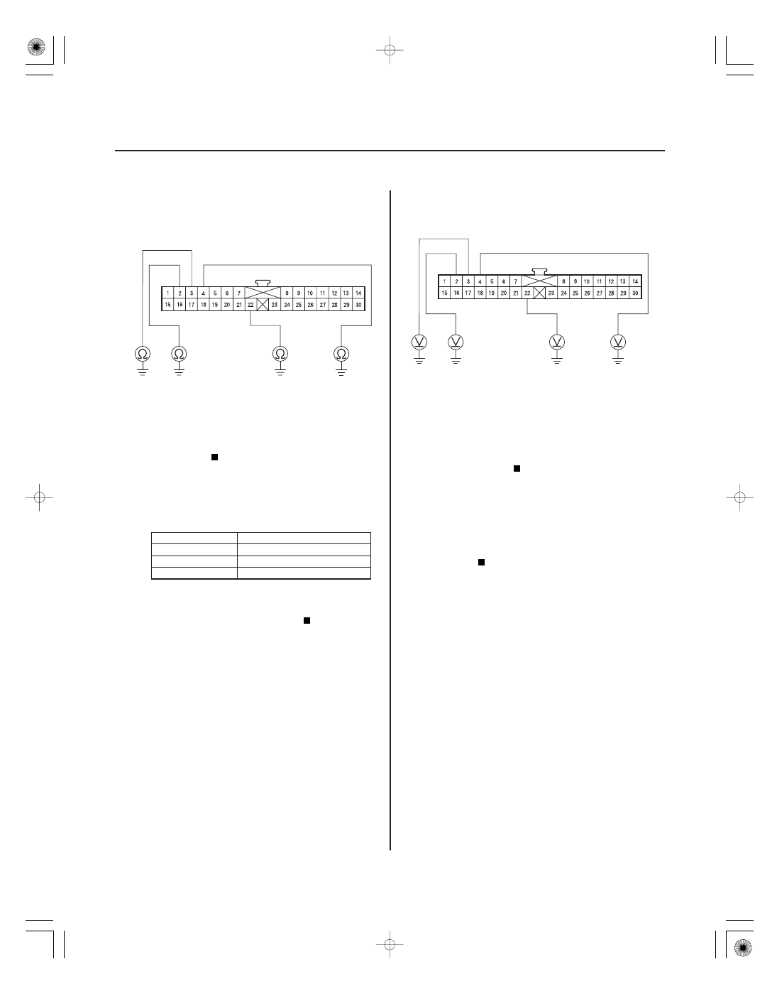
CLIMATE CONTROL UNIT 30P CONNECTOR
WHT/
BLU
RED/BLU
RED/YEL
RED/BLK
CLIMATE CONTROL UNIT 30P CONNECTOR
WHT/
BLU
RED/BLU
RED/YEL
RED/BLK
9. Check for continuity between body ground and the
climate control unit 30P connector No. 2, 3, 4, and
22 terminals individually.
Repair short to body ground in the wires
between the climate control unit and the mode
control motor.
Go to step 10.
10. Check for continuity between the climate control
unit 30P connector terminals as follows.
From terminal
To terminals
2
3, 4, 22
3
4, 22
4
18, 22
Repair the short in the wires.
Go to step 11.
11. Turn the ignition switch ON (II), and check the same
terminals for voltage to body ground.
Repair short to power in the wires between
the climate control unit and the mode control motor.
This short may also damage the climate control
unit. Repair the short to power before replacing the
climate control unit.
Check for loose wires or poor connections at
the climate control unit 30P connector and at the
mode control motor 7P connector. If the
connections are good, substitute a known-good
climate control unit, and recheck. If the symptom/
indication goes away, replace the original climate
control unit.
Wire side of female terminals
Wire side of female terminals
Is ther e continuity?
Is ther e continuity?
Is ther e any voltage?