Honda Ridgeline. Manual - part 412
01
How to Use the Self-diagnostic Function without the HDS
Canceling the Self-diagnostic Function
21-84
Climate Control
General Troubleshooting Information (cont’d)
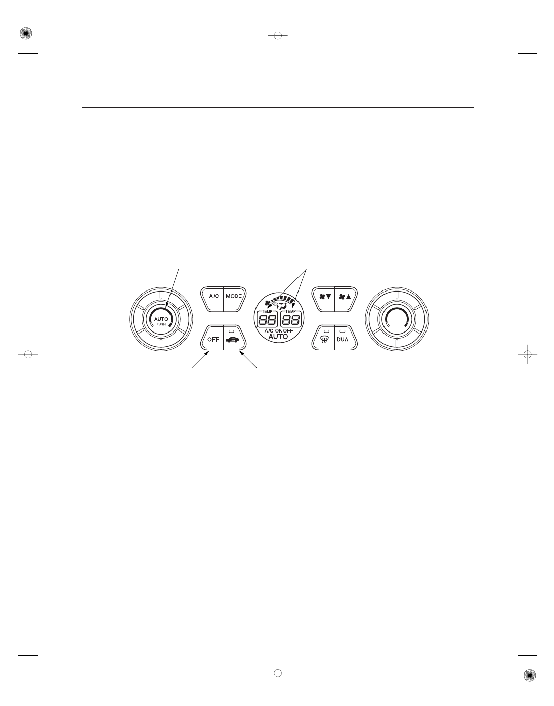
AUTO BUTTON
OFF BUTTON
RECIRCULATION BUTTON
TEMPERATURE INDICATOR
The climate control unit has a self-diagnostic function. To run the self-diagnostic function, do the following.
NOTE: Before troubleshooting the climate control system, refer to B-CAN System Diagnosis Test Mode A
Troubleshooting (see page 22-99), and the communication circuit self-diagnostic function test.
1. Turn the ignition switch OFF, and then ON (II).
2. Press and hold the OFF button. While holding the OFF button, press the recirculation button five times within
10 seconds. Release the OFF button, then the self-diagnostic begins. Wait for about one minute for the self-
diagnostic to complete.
NOTE: The blower motor will run various speeds regardless of what the panel is displaying.
• If there is any problem in the system, the temperature indicator will light up the segment (A through Q)
corresponding to the error. The temperature indicator will then alternate every second between displaying ‘‘88’’ (all
segments lit) and the error code segment (A through Q). To determine the meaning of the DTC, refer to checking for
DTCs.
• If there are no problems detected, the segments will not illuminate, and the system will appear to be turned off.
3. Turn the ignition switch OFF to cancel the self-diagnostic function. After completing repair work, run the self-
diagnostic function again to make sure that there are no other malfunctions.