Honda Ridgeline. Manual - part 406


  Index      Honda     Honda Ridgeline - service repair manual 2006-2008 year


Search            


Content   ..  404  405  406  407   ..


Honda Ridgeline. Manual - part 406


01

SJC8A00G24113600000KBAT00

01

02

SJC8A00G10123625311KBAT80

21-60

21-60

Heating/Air Conditioning

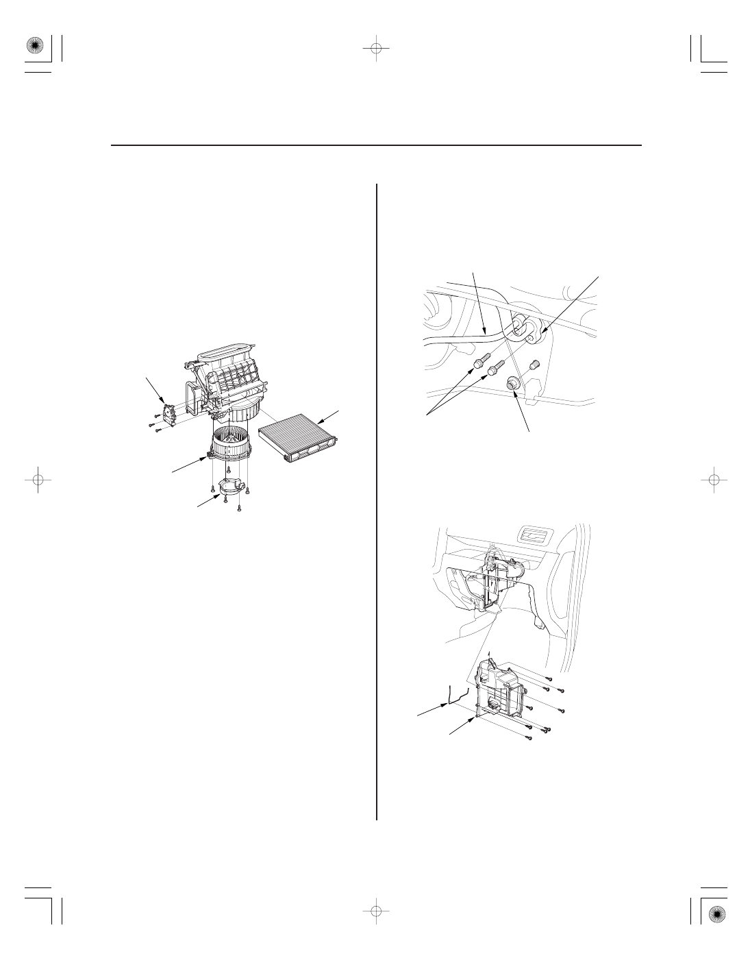
Blower Unit Component
Replacement

Evaporator Core Replacement

D

C

B

A

6 x 1.0 mm
9.8 N·m
(1.0 kgf·m, 7.2 lbf·ft)

8 x 1.25 mm
12.3 N·m
(1.3 kgf·m, 9.1 lbf·ft)

B

A

B

A

Note these items when overhauling the blower unit:

• The recirculation control motor (A), the blower motor

cover (B), blower motor (C), and the dust and pollen
filter (D) can be replaced without removing the
blower unit.

• Before reassembly, make sure that the recirculation

control linkage and door move smoothly without
binding.

• After reassembly, make sure the recirculation control

motor runs smoothly (see page 21-57).

1. Recover the refrigerant with a recovery/recycling/

charging station (see page 21-73).

2. Remove the bolts and nut, then disconnect the

suction line (A) and the receiver line A (B) from the
evaporator core.

3. Remove the blower unit (see page 21-59).

4. Remove the self-tapping screws, the joint duct (A)

and the seal (B).

03

04

21-61

A

B

A

B

5. Remove the bolts, inlet and outlet pipes (A), and

expansion valve (B).

6. Carefully pull out the evaporator core (A) and the

plate (B).

7. Install the core in the reverse order of removal, and

note these items:

• If you’re installing a new evaporator core, add

refrigerant oil (DENSO ND-OIL 8) (see page 21-6).

• Replace the O-rings with new ones at each fitting,

and apply a thin coat of refrigerant oil before
installing them. Be sure to use the correct O-rings
for HFC-134a (R-134a) to avoid leakage.

• Immediately after using the oil, reinstall the cap

on the container, and seal it to avoid moisture
absorption.

• Do not spill the refrigerant oil on the vehicle; it

may damage the paint; if the refrigerant oil
contacts the paint, wash it off immediately.

• Make sure that there is no air leakage.
• Charge the system (see page 21-75).

01

02

03

SJC8A00G24100031461KBAT80

21-62

Heating/Air Conditioning

Heater Unit/Core Replacement

A

B

C

6 x 1.0 mm
9.8 N·m
(1.0 kgf·m, 7.2 lbf·ft)

A

B

C

D

8 x 1.25 mm
12.3 N·m
(1.3 kgf·m, 9.1 lbf·ft)

SRS components are located in this area. Review the
SRS component locations (see page 24-14) and the
precautions and procedures (see page 24-16) before
repairing or servicing.

1. Make sure you have the anti-theft code for the

audio or the navigation system, then write down
the audio presets.

2. Make sure the ignition is OFF, then disconnect the

negative cable from the battery.

3. Disconnect the suction and receiver lines from the

evaporator core (see page 21-60).

4. From under the hood, open the cable clamp (A),

then disconnect the heater valve cable (B) from the
heater valve arm (C). Turn the heater valve arm to
the fully opened position as shown.

5. When the engine is cool, drain the engine coolant

from the radiator (see page 10-6).

6. Slide the hose clamps (A) back. Remove the nut

and the water valve (B), then disconnect the inlet
heater hose (C) and the outlet heater hose (D) from
the heater unit. Engine coolant will run out when
the hoses are disconnected; drain it into a clean
drip pan. Be sure not to let coolant spill on the
electrical parts or the painted surfaces. If any
coolant spills, rinse it off immediately.

7. Remove the mounting nut from the heater unit.

Take care not to damage or bend the fuel lines and
the brake lines, etc.

04

05

06

07

21-63

A

B

B

A

A

C

B

6 x 1.0 mm
9.8 N·m (1.0 kgf·m, 7.2 lbf·ft)

A

8. Remove the dashboard (see page 20-89).

9. Disconnect the connectors (A) from the blower

motor and the power transistor, then remove the
wire harness clips (B).

10. Disconnect the connectors (A) from the mode

control motor and the recirculation control motor,
then remove the wire harness clips (B).

11. Disconnect the connectors (A) from the evaporator

sensor and the air mix control motor, then remove
the wire harness clips (B) and the wire harness (C).

12. Remove the mounting nuts and the blower-heater

unit (A).

(cont’d)


Content   ..  404  405  406  407   ..