Honda Ridgeline. Manual - part 403


  Index      Honda     Honda Ridgeline - service repair manual 2006-2008 year


Search            


Content   ..  401  402  403  404   ..


Honda Ridgeline. Manual - part 403


03

04

YES

NO

21-48

Heating/Air Conditioning

A/C Compressor Clutch Circuit Troubleshooting (cont’d)
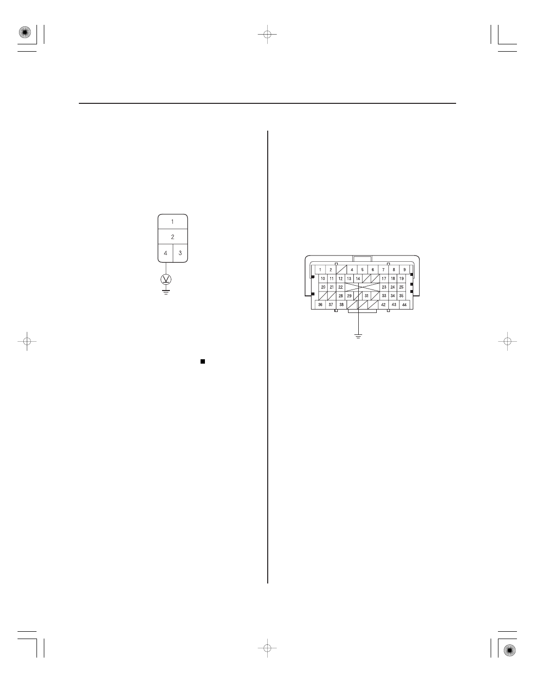
BLK/YEL

A/C COMPRESSOR CLUTCH RELAY 4P SOCKET

PCM CONNECTOR A (44P)

JUMPER WIRE

RED

10. Disconnect the jumper wire.

11. Turn the ignition switch ON (II).

12. Measure the voltage between the A/C compressor

clutch relay 4P socket No. 4 terminal and body
ground.

Go to step 13.

Repair open in the wire between the No. 30

(7.5 A) fuse in the under-dash fuse/relay box and
the A/C compressor clutch relay.

13. Turn the ignition switch OFF.

14. Reinstall the A/C compressor clutch relay.

15. Jump the SCS line with the HDS.

NOTE: This step must be done to protect the
powertrain control module (PCM) from damage.

16. Disconnect PCM connector A (44P).

17. Connect the PCM connector A (44P) No. 14 terminal

to body ground with a jumper wire.

Terminal side of female terminals

Is ther e batter y voltage?

05

01

SJC8AH6G10100012062FAAT80

YES

NO

YES

NO

YES

NO

YES
NO

YES
NO

21-49

21-49

A/C Pressure Switch Circuit
Troubleshooting

A/C COMPRESSOR CLUTCH RELAY 4P SOCKET

BLU/RED

A/C COMPRESSOR CLUTCH 1P CONNECTOR

BLU/RED

A/C PRESSURE SWITCH 4P CONNECTOR

BLU/RED

18. Turn the ignition switch ON (II).

Check for loose wires or poor connections at

PCM connector A (44P). If the connections are good,
check the PCM grounds. If the grounds are good,
substitute a known-good PCM, and recheck. If the
symptom/indication goes away, replace the
original PCM (see page 11-205).

Repair open in the wire between the A/C

compressor clutch relay and the PCM.

19. Disconnect the jumper wire.

20. Disconnect the A/C compressor clutch 1P connector.

21. Check for continuity between the A/C compressor

clutch relay 4P socket No. 2 terminal and the A/C
compressor clutch 1P connector No. 1 terminal.

Check the A/C compressor clutch clearance,

and the compressor clutch field coil (see page
21-68). Repair as needed.

Repair open in the wire between the A/C

compressor clutch relay and the A/C compressor
clutch.

NOTE:

• Do not use this troubleshooting procedure if any of

the following items are operative; A/C condenser fan,
radiator fan, A/C compressor. Refer to the symptom
troubleshooting index.

• Before doing any symptom troubleshooting, check

for powertrain DTCs (see page 11-3).

• If the blower motor does not run at all speeds, the A/C

compressor will be inoperative. Before performing
any other troubleshooting, repair the cause of the
inoperative blower motor.

1. Check for body DTCs using B-CAN system

diagnosis test mode A troubleshooting (see page
22-99).

Do the appropriate troubleshooting for the

DTC indicated.

Go to step 3.

2. Refer to the PGM-FI ECU Data List.

Go to step 3.

Refer to the symptom troubleshooting

index.

3. Disconnect the A/C pressure switch 4P connector.

4. Turn the ignition switch ON (II).

5. Measure the voltage between the A/C pressure

switch 4P connector No. 4 terminal and body
ground.

Go to step 6.

Go to step 20.

(cont’d)

Terminal side of male terminals

Wire side of female terminals

Does the A/ C compr essor click?

Is ther e continuity?

Ar e ther e any DT Cs indicated?

Is the A/ C switch of f ?

Is ther e 5 V or mor e?

07

02

03

04

YES

NO

YES

NO

YES

NO

YES

NO

21-50

Heating/Air Conditioning

A/C Pressure Switch Circuit Troubleshooting (cont’d)

A/C PRESSURE SWITCH 4P CONNECTOR

BLU/RED

JUMPER WIRE

A/C PRESSURE SWITCH

HVAC CONTROL UNIT 30P CONNECTOR

YEL

HVAC CONTROL UNIT 30P CONNECTOR

BRN

RED/BLK

6. Connect the A/C pressure switch 4P connector

No. 4 terminal to body ground with a jumper wire.

7. Start the engine.

Go to step 8.

Check the connection of under-hood fuse/

relay box connector H (18P) No. 3 terminal. If the
connection is OK, replace the under-hood fuse/
relay box (see page 22-72).

8. Disconnect a jumper wire, and turn the ignition

switch OFF.

9. Check for continuity between the A/C pressure

switch No. 1 and No. 4 terminals.

Go to step 10.

Go to step 19.

10. Reconnect the A/C pressure switch 4P connector.

11. Disconnect the HVAC control unit 30P connector.

12. Turn the ignition switch ON (II).

13. Measure the voltage between the HVAC control

unit 30P connector No. 12 terminal and body
ground.

Go to step 14.

Repair the open in the wire between the

HVAC control unit and the A/C pressure switch.

14. Turn the ignition switch OFF.

15. Measure the evaporator temperature sensor

resistance between the HVAC control unit 30P
connector No. 20 and No. 24 terminals.

Go to step 16.

Test the evaporator temperature sensor

(see page 21-53).

Wire side of female terminals

Wire side of female terminals

Wire side of female terminals

Does the compr essor and f ans come on?

Is ther e continuity?

Is ther e 5 V or mor e?

Is the r esistance less than 24 k

?

05

06

YES

NO

YES

NO

YES

NO

YES

NO

21-51

UNDER-HOOD RELAY BOX CONNECTOR H (18P)

A/C PRESSURE SWITCH 4P CONNECTOR

BLU/RED

BLU/RED

A/C PRESSURE SWITCH 4P CONNECTOR

BLU/RED

JUMPER WIRE

16. Reconnect the HVAC control unit 30P connector.

17. Turn the ignition switch ON (II).

18. Check that blower motor operates at all speeds.

Check for loose wires or poor connections at

the HVAC control unit 30P connector and at the A/C
pressure switch 4P connector. If the connections
are good, substitute a known-good HVAC control
unit and recheck. If the symptom/indication goes
away, replace the original HVAC control unit.

Repair the problem in the blower motor

circuit.

19. Check for proper A/C system pressure.

Replace the A/C pressure switch.

Repair the A/C pressure problem.

20. Disconnect under-hood relay box connector H (18P).

21. Check for continuity between the A/C pressure

switch connector No. 4 terminal and under-hood
relay box connector H (18P) No. 3 terminal.

Go to step 22.

Repair open in the wire between the relay

control module and the A/C pressure switch.

22. Reconnect under-hood relay box connector H (18P).

23. Connect the A/C pressure switch connector No. 4

terminal to body ground with the jumper wire.

24. Start the engine.

Replace the relay control module.

Check for loose wires or poor connections. If

the connections are good, check the grounds. If the
grounds are good, replace the relay control
module.

Wire side of female terminals

Wire side of female terminals

Wire side of female terminals

Does the blower motor oper ate at all speeds?

Is the pr essur e within specif ications?

Is ther e continuity?

Do the A/ C compr essor and f ans come on?


Content   ..  401  402  403  404   ..