Honda Ridgeline. Manual - part 401
01
02
SJC8A00G10110249112FAAT10
−
−
−
−
−
−
−
−
−
−
YES
NO
YES
NO
YES
NO
YES
NO
YES
NO
21-40
Heating/Air Conditioning
Radiator and A/C Condenser Fan Low Speed Circuit Troubleshooting
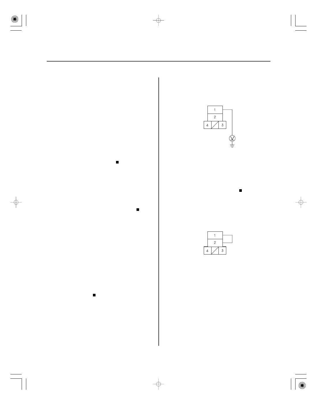
A/C CONDENSER FAN RELAY 4P SOCKET
YEL/GRN
A/C CONDENSER FAN RELAY 4P SOCKET
YEL/GRN
BLU/YEL
JUMPER WIRE
NOTE:
• Do not use this troubleshooting procedure if the A/C
compressor is inoperative. Refer to the symptom
troubleshooting index.
• Before performing symptom troubleshooting, check
for powertrain DTCs (see page 11-3).
1. Check the No. 20 (30 A) fuse in the under-hood
fuse/relay box, and the No. 30 (7.5 A) fuse in the
under-dash fuse/relay box.
Go to step 2.
Replace the fuses, and recheck. If the fuses
blow again, check for a short in the No. 20 (30 A)
and No. 30 (7.5 A) fuses circuit.
2. Remove the A/C condenser fan relay from the
auxiliary under-hood fuse/relay box, and test it
(see page 22-75).
Go to step 3.
Replace the A/C condenser fan relay.
3. Connect the HDS to the DLC (see page 21-8).
4. Turn the ignition switch ON (II).
5. Turn on the A/C on the HVAC control unit.
6. Check the FAN LOW CTRL in the PGM-FI Data List
with the HDS.
Go to step 7.
Substitute a known-good PCM (see page 11-8),
and retest. If the symptom/indication goes away
with a known-good PCM, replace the original PCM
(see page 11-205).
7. Measure the voltage between the A/C condenser
fan relay 4P socket No. 1 terminal and body ground.
Go to step 8.
Repair open in the wire between the No. 20
(30 A) fuse in the auxiliary under-hood fuse/relay
box and the A/C condenser fan relay.
8. Connect the A/C condenser fan relay 4P socket
No. 1 and No. 2 terminals with a jumper wire.
Go to step 9.
Go to step 18.
Ar e the f uses OK ?
Is the r elay OK ?
Is the F AN LOW CT RL on?
Is ther e batter y voltage?
Do the A/ C condenser and r adiator f ans r un?