Honda Ridgeline. Manual - part 399
*01
SJC8AH6K733000Y1240FAAT00
−
−
−
−
−
−
DTC B1240 or DTC indicator 5:
YES
NO
YES
NO
YES
NO
21-32
Heating/Air Conditioning
DTC Troubleshooting (cont’d)
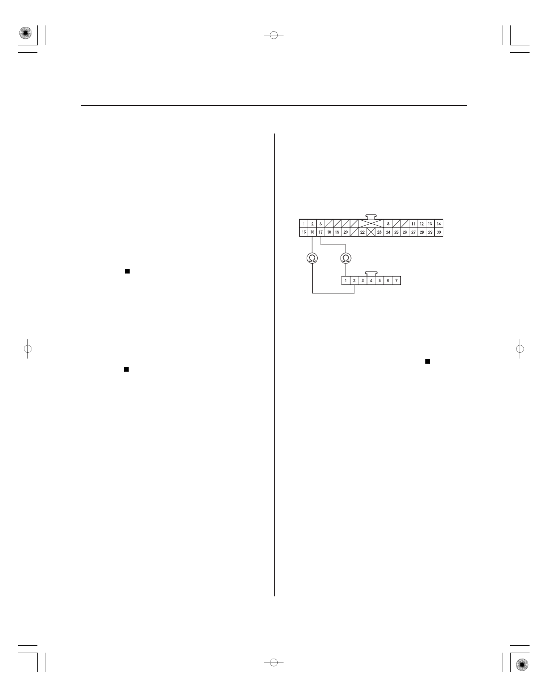
HVAC CONTROL UNIT 30P CONNECTOR
YEL/RED
MODE CONTROL MOTOR 7P CONNECTOR
YEL/BLU
YEL/RED
YEL/BLU
A Problem in
the Mode Control Linkage, Doors, or Motor
1. Clear the DTC with the HDS.
2. Operate the heater-A/C control system in several
modes.
3. Check for DTCs using the HDS or self-diagnostic.
Go to step 4.
Intermittent failure, check for loose wires or
poor connections on the mode control motor
circuit.
4. Turn the ignition switch OFF.
5. Test the mode control motor (see page 21-56).
Go to step 6.
Replace the mode control motor (see page
21-56), or repair the mode control linkage or
doors.
6. Disconnect the mode control motor 7P connector.
7. Disconnect HVAC control unit 30P connector.
8. Check for continuity between the following
terminals of HVAC control unit 30P connector and
the mode control motor 7P connector.
30P:
7P:
No. 16
No. 2
No. 17
No. 1
Go to step 9.
Repair open in the wire(s) between the HVAC
control unit and the mode control motor.
Wire side of female terminals
Wire side of female terminals
Is DT C B1240 or 5 indicated?
Is the mode contr ol motor OK ?
Is ther e continuity?