Honda Ridgeline. Manual - part 393
01
SJC8AH6G24100032585BBAT00
How to Check for DTCs with the HDS
21-8
Heating/Air Conditioning
General Troubleshooting Information
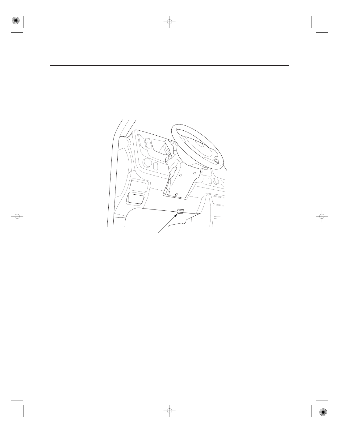
A
1. Make sure the ignition switch is OFF.
2. Connect the HDS to the data link connector (DLC) (A) located under the driver’s side of the dashboard.
3. Turn the ignition switch ON (II).
4. Make sure the HDS communicates with the vehicle and the climate control unit. If it doesn’t, troubleshoot the DLC
circuit (see page 11-194).
5. Select HVAC/CLIMATE CONTROL in the BODY ELECTRICAL menu.
6. Select DTCs in the HVAC/CLIMATE CONTROL menu.
7. Check for DTCs. If any DTCs are indicated, write down the DTCs, then go to the indicated DTC troubleshooting. If
no DTCs are indicated, refer to symptom troubleshooting.
NOTE:
• After troubleshooting, clear the DTCs with the HDS.
• For specific operations, refer to the user’s manual that came with the HDS.