Honda Ridgeline. Manual - part 364
02
03
04
05
06
Driver’s side
Passenger’s side
20-94
Dashboard
Dashboard/Steering Hanger Beam Disassembly/Reassembly (cont’d)
A
B
A
A
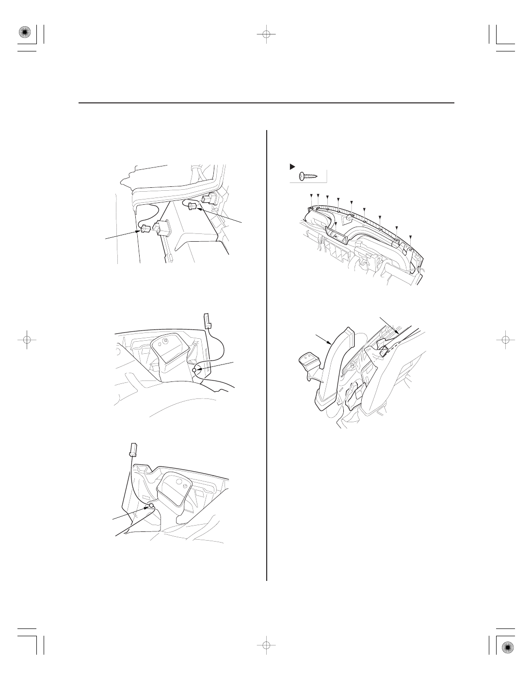
Fastener Locations
: Screw, 10
A
B
4. From the back of the dashboard, disconnect the
AUX jack connector (A) and in-bed trunk lid main
switch connector (B).
5. From the back of the dashboard, detach the tweeter
harness clip (A).
6. From the back of the dashboard, remove the
screws.
7. Slide the defogger duct (A), and remove the
passenger’s A/C duct (B).