Honda Ridgeline. Manual - part 362


  Index      Honda     Honda Ridgeline - service repair manual 2006-2008 year


Search            


Content   ..  360  361  362  363   ..


Honda Ridgeline. Manual - part 362


03

01

SJC8A00J26220230118KBAT00

20-86

20-86

Dashboard

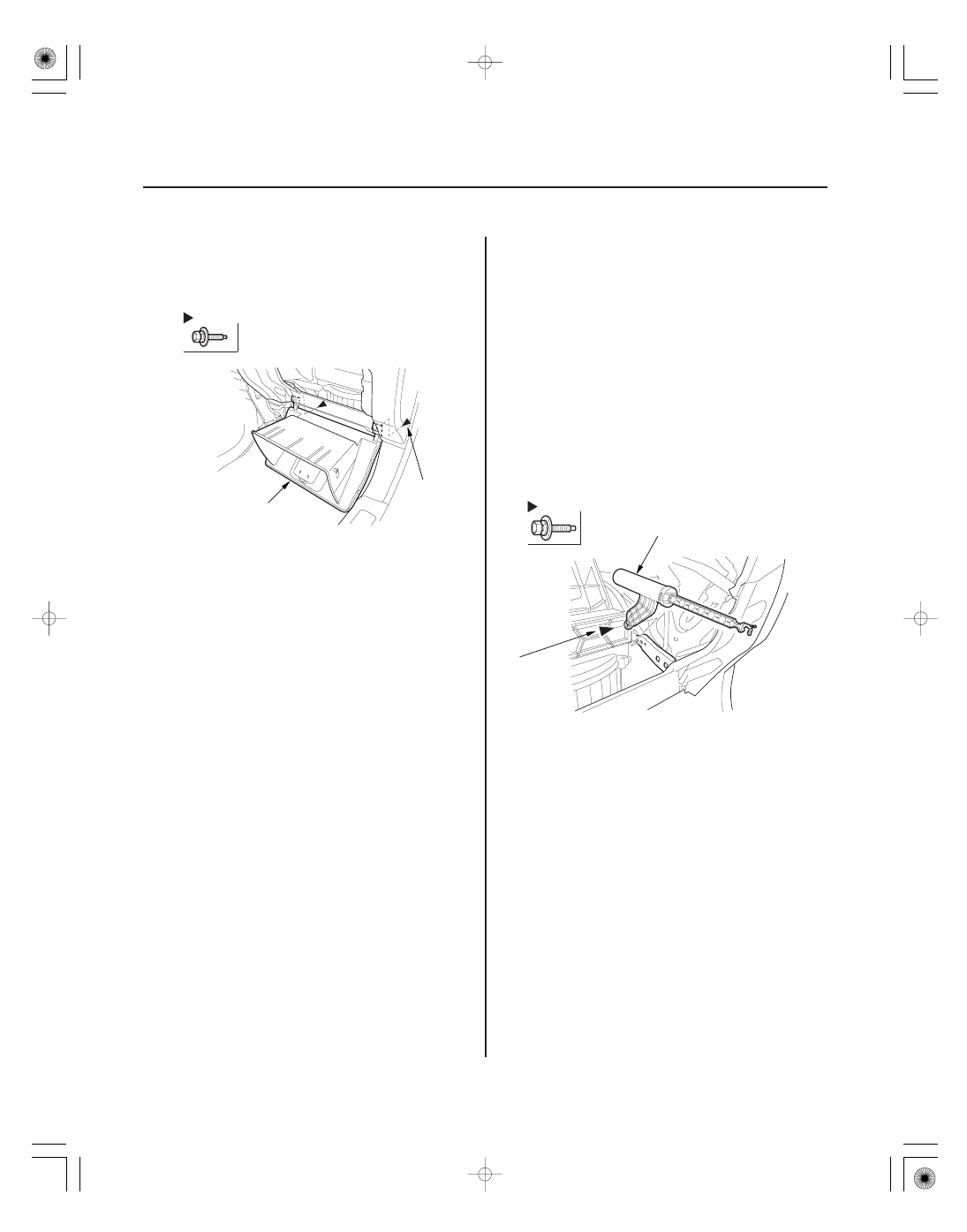
Glove Box Removal/Installation
(cont’d)

Glove Box Damper Replacement

Fastener Locations

: Bolt, 2

A

5 x 0.8 mm
5 N·m
(0.5 kgf·m,
4 lbf·ft)

Fastener Location

: Bolt, 1

A

5 x 0.8 mm
4 N·m
(0.4 kgf·m,
3 lbf·ft)

3. Remove the bolts, then remove the glove box (A).

4. Install the glove box in the reverse order of

removal.

SRS components are located in this area. Review the
SRS component locations (see page 24-14) and the
precautions and procedures (see page 24-16) before
doing repairs or service.

NOTE: Take care not to scratch the dashboard and
related parts.

1. While holding the glove box, remove the glove box

stop on each side (see step 1 on page 20-85).

2. Disconnect the glove box damper from the glove

box (see step 2 on page 20-85).

3. Remove the bolt, then remove the glove box

damper (A).

4. Install the glove box damper in the reverse order of

removal.

01

SJC8A00J26220230114KBAT00

01

SJC8A00J26220230099KBAT02

20-87

20-87

Glove Box Lock Replacement

Glove Box Striker Bracket
Replacement

Fastener Locations

: Screw, 2

A

Fastener Locations

: Screw, 2

B

: Screw, 4

D

A

B

C

D

E

D

D

D

B

NOTE: Take care not to scratch the glove box and
related parts.

1. Open the glove box.

2. Remove the screws, then remove the glove box

lock (A).

3. Install the glove box lock in the reverse order of

removal.

SRS components are located in this area. Review the
SRS component locations (see page 24-14) and the
precautions and procedures (see page 24-16) before
doing repairs or service.

NOTE: Take care not to scratch the dashboard and
related parts.

1. While holding the glove box, remove the glove box

stop on each side (see step 1 on page 20-85).

2. Disconnect the glove box damper from the glove

box (see step 2 on page 20-85).

3. Detach the harness clips (A), and remove the

screws (B), then remove the glove box light (C).

4. Remove the screws (D), then remove the glove box

striker bracket (E).

5. Install the glove box striker bracket in the reverse

order of removal.

01

02

SJC8A00J26220245405KBAT00

01

02

SJC8A00J26220219251KDAT00

Special Tools Required

Center

Outer

20-88

20-88

Dashboard

Passenger’s Tray Replacement

Dashboard Vent Removal/
Installation

A

Fastener Locations

: Screw, 2

Fastener Locations

: Screw, 8

A

A

A

NOTE:

• Put on gloves to protect your hands.
• Take care not to scratch the passenger’s tray and

related parts.

1. Remove the steering hanger beam from the

dashboard (see page 20-93).

2. Remove the glove box striker bracket (see page

20-87).

3. Remove the screws, then remove the right

dashboard center stay (A).

4. Remove screws, then remove the passenger’s tray

(A).

5. Install the passenger’s tray in the reverse order of

removal.

KTC trim tool set SOJATP2014

Available through the American Honda Tool and
Equipment Program; call 888-424-6857

SRS components are located in this area. Review the
SRS component locations (see page 24-14) and the
precautions and procedures (see page 24-16) before
doing repairs or service.

NOTE:

• Take care not to scratch the dashboard and related

parts.

• Use the appropriate tool from the KTC trim tool set to

avoid damage when prying components.

• Put on gloves to protect your hands.

1. While holding the glove box, remove the glove box

stop on each side (see step 1 on page 20-85).

2. Disconnect the glove box damper from the glove

box (see step 2 on page 20-85).

3. To loosen, push on the dashboard vent (A) by

reaching through the glove box opening.

03

04

SJC8A00J26220200000KDAT00

Center

Outer

Special Tools Required

20-89

20-89

Dashboard/Steering Hanger Beam
Removal/Installation

A

B

C

C

C

A

B

C

C

C

4. Insert the trim tool into a gap between the

dashboard vent (A) and the dashboard (B), and
release the hooks (C).

5. Install the dashboard vent in the reverse order of

removal.

KTC trim tool set SOJATP2014

Available through the American Honda Tool and
Equipment Program; call 888-424-6857

SRS components are located in this area. Review the
SRS component locations (see page 24-14) and the
precautions and procedures (see page 24-16) before
doing repairs or service.

NOTE:

• Use the appropriate tool from the KTC trim tool set to

avoid damage when prying components.

• Have an assistant help you when removing and

installing the dashboard.

• Take care not to scratch the dashboard, body and

other related parts.

• Put on gloves to protect your hands.

1. Make sure you have the anti-theft codes for the

audio system and the navigation system (if
equiped).

2. Disconnect the negative cable from the battery, and

wait at least 3 minutes before beginning work.

3. Remove these items:

• Driver’s dashboard lower cover (see page 20-83)
• Dashboard center lower cover (see page 20-84)
• Center console (see page 20-76)
• Glove box (see page 20-85)
• Driver’s dashboard side cover (see page 20-83)
• Kick panels, both sides (see page 20-60)
• A-pillar trim, both sides (see page 20-63)
• Steering column (see page 17-24)

4. Disconnect the A/T shift cable (see page 14-261).

(cont’d)


Content   ..  360  361  362  363   ..