Honda Ridgeline. Manual - part 361


  Index      Honda     Honda Ridgeline - service repair manual 2006-2008 year


Search            


Content   ..  359  360  361  362   ..


Honda Ridgeline. Manual - part 361


03

04

05

20-82

Dashboard

Instrument Panel Removal/Installation (cont’d)

A

B

C

D

E

F

G

H

Fastener Locations

: Screw, 3

A

B

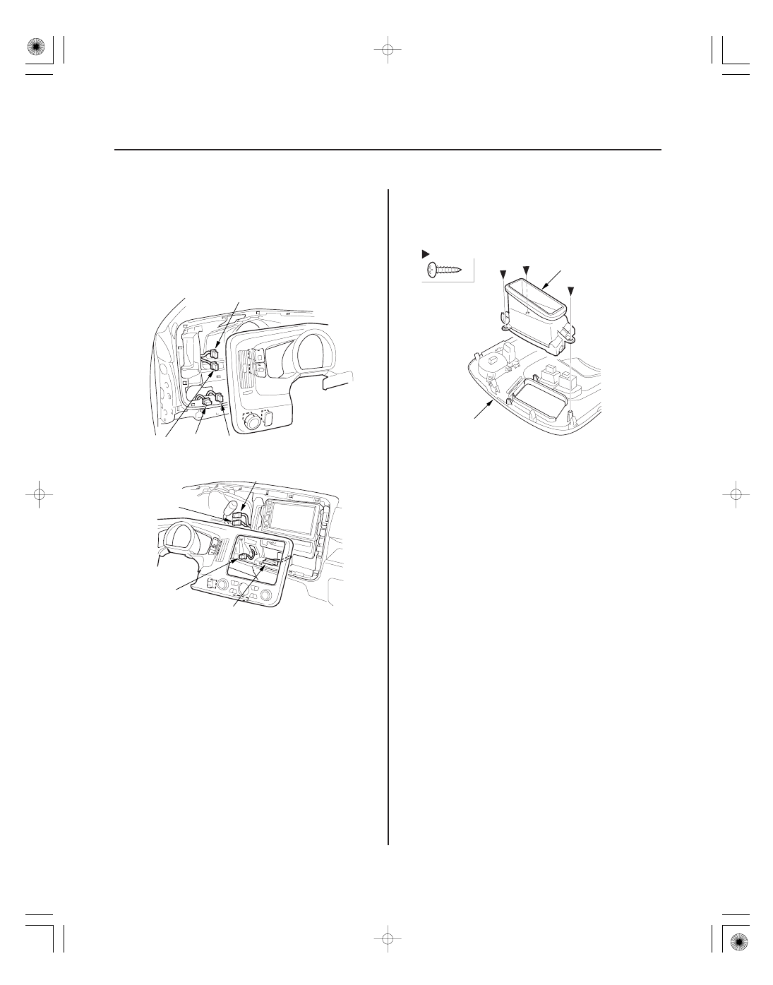
5. Disconnect the headlight switch connector (A),

cargo lights switch connector (B), illumination
switch connector (C), moonroof switch connector
(D) (for some models), VTM-4 lock switch
connector (E), select/reset information switch
connector (F), interior lights switch connector (G),
and climate control unit connector or HVAC control
unit connector (H).

6. If necessary, remove the screws securing the

driver’s vent (A), then remove the driver’s vent
from the instrument panel (B).

7. Install the panel in the reverse order of removal,

and note these items:

• Make sure all connectors are plugged in properly.
• Check if the clips are damaged or stress-

whitened, and if necessary, replace them with
new ones.

• Push the clips and hooks into place securely.

01

02

SJC8A00J26220219301KDAT10

Special Tools Required

20-83

Driver’s Dashboard Lower Cover Removal/Installation

A

B

C

D

E

E

Fastener Locations

: Screw, 1

B

: Clip, 9

C

B

C

F

C

C

C

C

C C

C

C

A

E

G

H

D

D

KTC trim tool set SOJATP2014

Available through the American Honda Tool and
Equipment Program; call 888-424-6857

NOTE:

• Use the appropriate tool from the KTC trim tool set to

avoid damage when prying components.

• Take care not to scratch the dashboard and related

parts.

• Put on gloves to protect your hands.

1. Open the front door, and remove the driver’s

dashboard side cover (A).

–1 Pull out the front door opening trim (B), as

necessary.

–2 Pry up on the lower edge of the dashboard side

cover at the notch (C) to release the clip (D).

–3 Gently pull out along the edge to release the

clips (E).

2. Remove the driver’s dashboard lower cover (A).

–1 Remove the screw (B) from the driver’s

dashboard lower cover.

–2 Pull out the bottom of the driver’s dashboard

lower cover to release the clips (C) and hooks
(D).

–3 Disconnect the VSA OFF switch connector (E),

the cruise control switch connector (F), the in-
car temperature sensor connector (G), and the
air hose (H).

3. Install the cover in the reverse order of removal,

and note these items:

• Make sure all connectors are plugged in properly,

and the air hose is connected properly.

• Check if the clips are damaged or stress-

whitened, and if necessary, replace them with
new ones.

• Push the clips and hooks into place securely.

01

02

03

SJC8A00J26220219281KDAT02

Special Tools Required

20-84

Dashboard

Dashboard Center Lower Cover Removal/Installation

Fastener Locations

: Clip, 5

Driver’s

Passenger’s

A

B

C

A

A

Fastener Locations

B

: Screw, 3

C

: Clip, 2

D

: Clip, 3

A

B

C

D

E

F

C

B

B

D

D

F

KTC trim tool set SOJATP2014

Available through the American Honda Tool and
Equipment Program; call 888-424-6857

SRS components are located in this area. Review the
SRS component locations (see page 24-14) and the
precautions and procedures (see page 24-16) before
doing repairs or service.

NOTE:

• Take care not to scratch the dashboard and related

parts.

• Use the appropriate tool from the KTC trim tool set to

avoid damage when prying components.

1. From under the dash, detach the clips, release the

guide (A), then remove the driver’s console side
trim (B) and passenger’s console side trim (C).

2. Open the center lower pocket (A), and remove it by

pulling the bottom of it up.

3. Remove the dashboard center lower cover (A).

–1 Remove the screws (B).
–2 Pull out the cover to release the clips (C, D).
–3 Disconnect the seat heater connectors (E) (for

some models) and accessory socket
connectors (F).

4. Install the cover in the reverse order of removal,

and note these items:

• Check if the clips are damaged or stress-

whitened, and if necessary, replace them with
new ones.

• Make sure the each connector is plugged in

properly.

• Push the clips into place securely.

01

SJC8A00J26220219281MFAT00

01

02

SJC8A00J26220230101KDAT00

20-85

20-85

Dashboard Center Lower Cover
Disassembly/Reassembly

Glove Box Removal/Installation

Fastener Locations

: Screw, 8

A

B

A

B

A

B

NOTE: Take care not to scratch the armrest.

1. Remove the dashboard center lower cover

(see page 20-84).

2. Remove the screws, then separate the dashboard

center lower cover (A) and dashboard center lower
cover bin (B).

3. Reassemble the cover in the reverse order of

disassemble, and make sure the accessory socket
connectors and seat heater connectors (for some
models) are plugged in properly.

SRS components are located in this area. Review the
SRS component locations (see page 24-14) and the
precautions and procedures (see page 24-16) before
doing repairs or service.

NOTE: Take care not to scratch the dashboard and
related parts.

1. While holding the glove box (A), remove the glove

box stop (B) on each side.

2. Disconnect the glove box damper (A) from the

glove box (B).

(cont’d)


Content   ..  359  360  361  362   ..