Honda Ridgeline. Manual - part 354


  Index      Honda     Honda Ridgeline - service repair manual 2006-2008 year


Search            


Content   ..  352  353  354  355   ..


Honda Ridgeline. Manual - part 354


08

09

20-54

Moonroof

Frame and Drain Tube Replacement (cont’d)

A

B

A

Upward

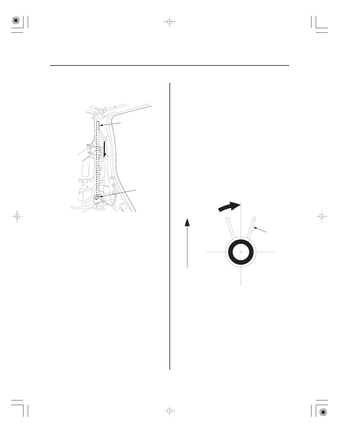
11. To remove the rear drain valve (A), tie a string to

the end of the drain tube (B), then pull the drain
tube down through the C-pillar.

12. Install the frame and drain tube in the reverse order

of removal, and note these items:

• Before installing the frame, clear the drain tubes

and drain valves using compressed air.

• When installing a drain tube, tie the string that

was pulling through the pillar during the
disassembly to the top end of the new drain tube,
pull it up through the pillar to the moonroof
frame.

• Check the frame seal.
• Clean the surface of the frame.
• When installing the frame, first attach the rear

hooks into the body holes.

• Make sure the connectors are plugged in

properly.

• When connecting the drain tube, slide it over the

frame nozzle at least 10 mm (0.39 in.).

• Install the tube clip (A) on the drain tube (B) as

shown.

• Make sure the clips are not rubbing on any parts

or body panels.

13. Check for water leaks. Let the water run freely from

a hose without a nozzle. Do not use a high-pressure
spray.

01

02

SJC8AB9J34200040702KBAT00

20-55

Drain Channel Slider and Cable Assembly Replacement

Fastener Locations

: Screw, 2

A

: Screw, 2

B

: Bolt, 2

E

: Screw, 2

F

A

B

C

D

E

F

G

6 x 1.0 mm
9.8 N·m
(1.0 kgf·m,
7.2 lbf·ft)

Forward

C

D

E

C

C

A

B

1. Remove the frame (see page 20-52).

2. Remove these parts from the frame:

• Sunshade (see page 20-50)
• Moonroof motor (see page 20-51)

3. Put on gloves to protect your hands. Remove the

screws (A, B) securing the slide stops (C), and cable
tube rear brackets (D), cable tube side bracket
mounting bolts (E) and the cable tube mounting
screws (F) from both sides of the frame (G).

4. Turn both cable tube side brackets (A) up to release

the hooks (B) from the holes in both sides of the
frame.

5. Pivot the glass brackets (C) down by sliding the link

lifters (D) back, then slide both glass brackets back
with the link lifters.

6. Slide the cable assembly (E) half-way.

(cont’d)

03

04

05

20-56

Moonroof

Drain Channel Slider and Cable Assembly Replacement (cont’d)

B

A

A

D

B

C

A

A

B

7. Remove the slide stops (A) and the drain channel

sliders (B) from both sides.

8. Slide the cable assembly (A) and both glass

brackets (B) back, remove the deflector sliders (C)
from both glass brackets, then remove them from
the frame (D).

9. Install the slider and cable assembly in the reverse

order of removal, and note these items:

• Damaged parts should be replaced.
• Apply multipurpose grease to the glass bracket

(A) and guide rail portion of the frame (B)
indicated by the arrows.

• Before reinstalling the motor, make sure both

link lifters are parallel, and in the fully closed
position.

• Before reinstalling the motor, install the frame

and glass, then check the opening drag (see page
20-58).

01

SJC8AB9J34200040951MBAT00

20-57

Limit Switch Adjustment

C
5 x 0.8 mm
5 N·m
(0.5 kgf·m, 4 lbf·ft)

A

B

D

E

F

G

E

1. Remove the headliner (see page 20-70).

2. With the moonroof wrench, close the glass (A) fully:

• Make sure both link lifters (B) are parallel, and in the position shown.
• Check the glass fit to the roof panel and the glass position (see page 20-47).

3. With an open-end wrench, loosen the limit switch mounting bolts (C).

4. Adjust the limit switch (D):

• Move the switch plate (E) a little at a time, then secure it at the position where you hear a faint click when the

switch cam (F) pushes the limit switch (open/close).

• Check that the switch plate contacts the switch bracket (G).

5. Check the operation of the glass (from the tilt-up position to fully closed position, from the fully open position to

the fully closed position) by operating the moonroof switch.

NOTE: Adjust the switch plate until the glass opens and closes correctly.

6. Reinstall all remaining parts in the reverse order of removal.


Content   ..  352  353  354  355   ..