Honda Ridgeline. Manual - part 338


  Index      Honda     Honda Ridgeline - service repair manual 2006-2008 year


Search            


Content   ..  336  337  338  339   ..


Honda Ridgeline. Manual - part 338


02

SJC8A00D52100000000FAAT08

YES

NO

YES

NO

YES

NO

YES

NO

YES

NO

YES

NO

VSA activation indicator does not come on
at start-up (bulb check)

19-89

19-89

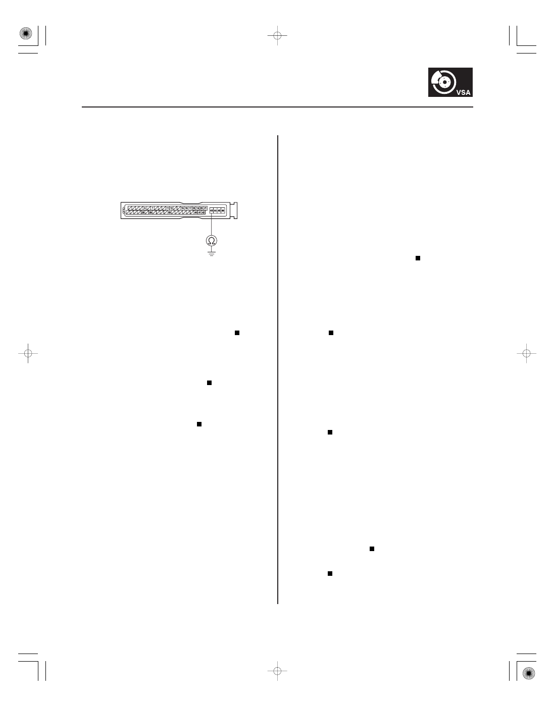
VSA MODULATOR-CONTROL UNIT 46P CONNECTOR

GND2
(BLK)

6. Check for continuity between VSA modulator-

control unit 46P connector terminal No. 43 and
body ground.

Go to step 7.

Repair open in the wire between the VSA

modulator-control unit and body ground.

7. Check for PGM-FI DTCs (see page 11-3).

Troubleshoot DTC U0155.

Check for loose terminal in the VSA

modulator-control unit 46P connector. If
connections are good, replace the VSA modulator-
control unit (see page 19-94).

If the VSA activation indicator does not come on and
the ABS indicator, VSA indicator, and brake system
indicator do not go off at the same time, do the ABS
indicator circuit troubleshooting first, then recheck.

1. Turn the ignition switch ON (II), and watch the VSA

activation indicator.

The system is OK at this time.

Go to step 2.

2. Check the DTCs with the HDS (see page 19-41).

Troubleshoot the DTC indicated, and

recheck.

Go to step 3.

3. Do the gauge control module self-diagnosis

function procedure (see page 22-244).

Go to step 4.

Replace the gauge control module (see page

22-263).

4. Turn the ignition switch OFF.

5. Substitute a known-good VSA modulator-control

unit (see page 19-94).

6. Turn the ignition switch ON (II), and watch the VSA

activation indicator.

Replace the original VSA modulator-control

unit (see page 19-94).

Replace the gauge control module (see page

22-263).

Wire side of female terminals

Is ther e continuity?

Is DT C U0155 indicated?

Does the V SA activation indicator come on and go
of f ?

Ar e DT C 91 or 92 indicated?

Is the gauge contr ol module OK ?

Does the V SA activation indicator come on and go
of f ?

01

SJC8A00D52100000000FAAT09

VSA activation indicator does not go off, and
no DTCs are stored

YES

NO

YES

NO

YES

NO

YES

NO

19-90

VSA System Components

Symptom Troubleshooting (cont’d)

VSA OFF SWITCH 10P CONNECTOR

RED/WHT

1. Turn the ignition switch ON (II), and watch the VSA

activation indicator.

The system is OK at this time.

Go to step 2.

2. Turn the ignition switch OFF.

3. Check the VSA OFF switch (see page 19-93).

Go to step 4.

Replace the VSA OFF switch (see page 19-93).

4. Remove the gauge control module (see page

22-263).

5. Disconnect gauge control module connector B

(14P).

6. Check for continuity between VSA OFF switch 10P

connector terminal No. 2 and body ground.

Repair short to body ground between the

gauge control module and the VSA OFF switch.

Go to step 7.

7. Check the gauge control module.

Replace the VSA modulator-control unit

(see page 19-94).

Replace the gauge control module (see page

22-263).

Wire side of female terminals

Does the V SA activation indicator go of f within
2 seconds?

Is the V SA OF F switch OK ?

Is ther e continuity?

Is the gauge contr ol module OK ?

01

SJC8A00D52100057091KBAT00

19-91

Steering Angle Sensor Replacement

A

B

NOTE: Do not damage or drop the combination switch as the steering angle sensor is sensitive to shock and vibration.

1. Make sure the ignition switch is OFF.

2. Remove the steering wheel (see page 17-21), and steering column cover (see step 6 on page 17-25).

3. Remove the combination switch assembly (see step 8 on page 17-25).

4. Remove the wiper/turn switch (A).

5. Replace the combination switch body complete (B).

6. Install the combination switch in the reverse order of removal.

NOTE: Do not remove the steering angle sensor from the combination switch body.

7. Do the steering angle sensor center point writing (see page 19-92).

SJC8A00D52100057091BBAT00

01

SJC8A00D52100068011KBAT00

19-92

19-92

VSA System Components

Steering Angle Sensor Center Point
Writing

Yaw Rate-Lateral Acceleration
Sensor Replacement

B

A

9.8 N·m
(1.0 kgf·m,
7.2 lbf·ft)

NOTE: Before doing the steering angle sensor center
point writing, place the vehicle on a flat level surface,
and turn the steering wheel to the straight ahead
position while moving the vehicle.

1. Connect the HDS to the DLC.

2. Select ABS TCS VSA, then ADJUSTMENTS, and

then CENTER POINT WRITING.

3. Verify DTC 84 clears and does not return. If DTC 84

is indicated, do the appropriate troubleshooting.

NOTE: Do not damage or drop the sensor as it is
sensitive.

1. Make sure the ignition switch is OFF.

2. Remove the rear console trim (see page 20-76).

3. Disconnect the yaw rate-lateral acceleration sensor

4P connector (A).

4. Remove the sensor mounting bolts, and remove

the yaw rate-lateral acceleration sensor (B).

5. Install in the reverse order of removal.


Content   ..  336  337  338  339   ..