Honda Ridgeline. Manual - part 335


  Index      Honda     Honda Ridgeline - service repair manual 2006-2008 year


Search            


Content   ..  333  334  335  336   ..


Honda Ridgeline. Manual - part 335


01

02

YES

NO

YES

NO

YES

NO

YES

NO

19-77

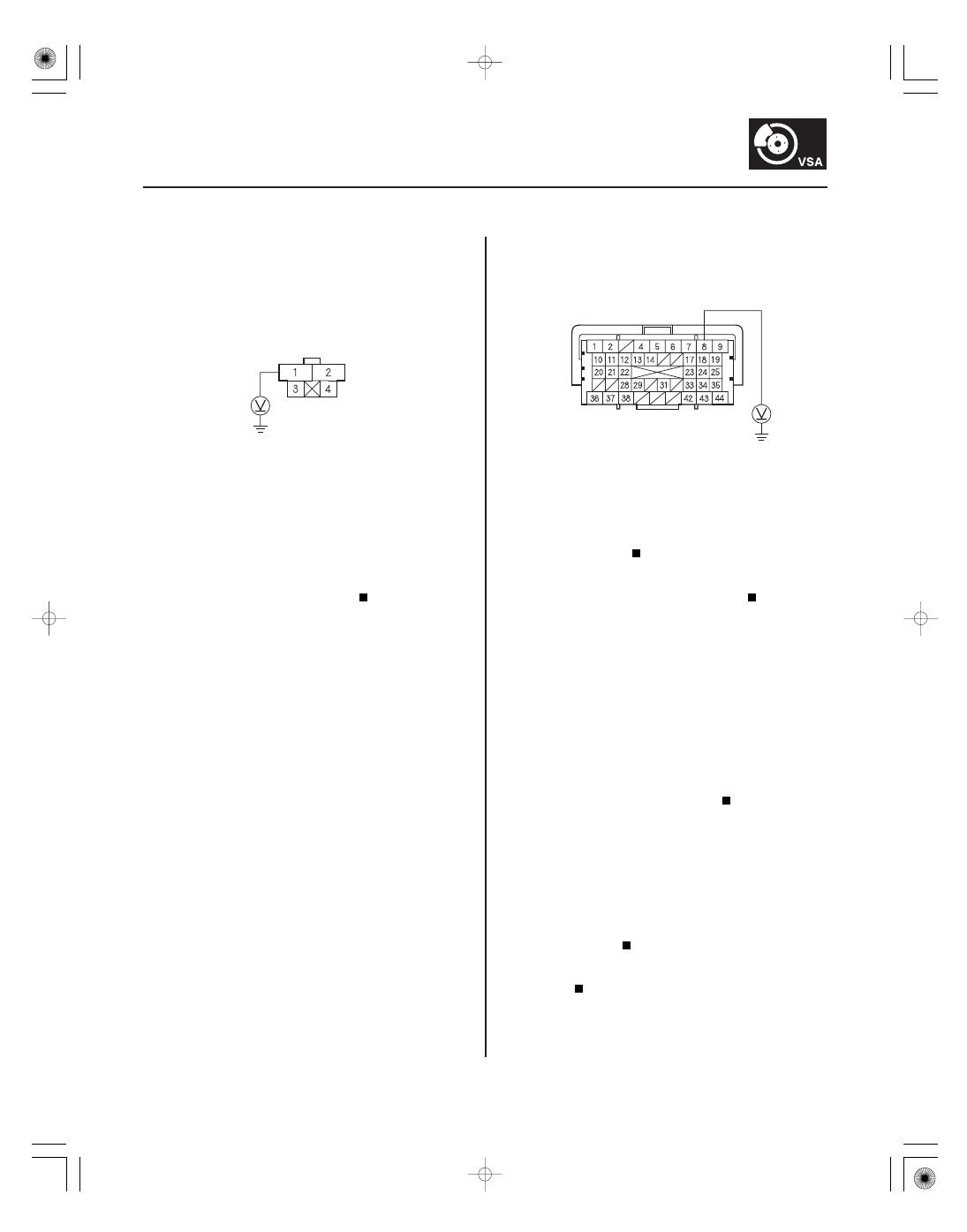
BRAKE PEDAL POSITION SWITCH 4P CONNECTOR

RED

PCM CONNECTOR A (44P)

BKSW (WHT/BLK)

5. Measure the voltage between brake pedal position

switch 4P connector terminal No. 1 and body
ground.

Go to step 6.

Repair open in the wire between the No. 13

(20 A) fuse in the under-hood fuse/relay box and
the brake pedal position switch.

6. Turn the ignition switch OFF, and jump the SCS line

with the HDS.

NOTE: This must be done to protect the powertrain
control module (PCM) from damage.

7. Disconnect PCM connector A (44P).

8. Measure the voltage between PCM connector

terminal A8 and body ground.

Substitute a known-good PCM (see page

11-8), and recheck.

Repair open in the wire between the brake

pedal position switch and the PCM (A8).

9. Clear the DTCs with the HDS (see page 19-41).

10. Turn the ignition switch OFF, then turn it ON (II),

and press the brake pedal several times.

11. Check for DTCs with the HDS (see page 19-41).

Go to step 12.

The system is OK at this time.

12. Check BRK PRESS in the VSA DATA LIST with the

HDS.

Replace the VSA modulator-control unit

(see page 19-94).

Check the brake lines for damage and

leakage.

Wire side of female terminals

Terminal side of female terminals

Is ther e batter y voltage?

Is ther e batter y voltage when the br ake pedal is
pr essed?

Does the ABS indicator come on, and is DT C 68
indicated?

Does BRK PRESS incr ease with the br ake pedal
pr essed and decr ease with the br ake pedal
r eleased?

±

SJC8A00K80100081720FAAT00

01

SJC8A00K80100081730FAAT00

DTC 72:

DTC 73:

YES

NO

YES

NO

YES

NO

YES

NO

YES

NO

YES

NO

19-78

19-78

VSA System Components

DTC Troubleshooting (cont’d)

YAW RATE-LATERAL ACCELERATION
SENSOR 4P CONNECTOR

IG1
(GRN/WHT)

Steering Angle Sensor

Yaw Rate Sensor (Power Supply)

1. Check for DTCs with the HDS.

Troubleshoot DTCs 91 or 92 and recheck.

Go to step 2.

2. Put the vehicle on a level surface, and center the

steering wheel spokes.

3. Check the STEERING ANGLE in the VSA DATA LIST

with the HDS.

Go to step 4.

Check for installation of the steering angle

sensor. If installation is good, do the steering angle
sensor center point writing.

4. Check the wheel alignment (see page 18-5).

Go to step 5.

Make sure the suspension is not modified,

and adjust the wheel alignment correctly, and
recheck by test-driving.

5. Clear the DTCs with the HDS (see page 19-41).

6. Turn the ignition switch OFF, then disconnect the

HDS.

7. Test-drive the vehicle around a number of corners.

8. Connect the HDS, and check for DTCs with the HDS

(see page 19-41).

Replace the VSA modulator-control unit

(see page 19-94).

Intermittent failure; the most probable cause

is that the vehicle has driven on an extremely
sloped road. The system is OK at this time.

1. Disconnect the yaw rate-lateral acceleration sensor

4P connector.

2. Turn the ignition switch ON (II).

3. Measure voltage between body ground and yaw

rate-lateral acceleration sensor 4P connector
terminal No. 1.

Go to step 5.

Repair open or high resistance in the wire

between the No. 31 (7.5 A) fuse in the under-dash
fuse/relay box and the yaw rate-lateral acceleration
sensor.

4. Turn the ignition switch OFF.

5. Reconnect the yaw rate-lateral acceleration sensor

4P connector.

6. Clear the DTCs with the HDS (see page 19-41).

7. Turn the ignition switch OFF, then turn it ON (II).

8. Check for DTCs with the HDS (see page 19-41).

Check for loose terminal in the yaw rate-

lateral acceleration 4P connector. If connection is
good, replace the VSA modulator-control unit
(see page 19-94).

Intermittent failure, the system is OK at this

time. Check for loose or poor connections.

Wire side of female terminals

Ar e DT Cs 91 or 92 indicated with DT C 7 2?

W ith the steer ing wheel in the str aight ahead
position, is ST EERING ANGLE within

5 °?

Is the wheel alignment within the specif ication?

Does the V SA indicator come on, and is DT C 7 2
indicated?

Is ther e batter y voltage?

Does the V SA indicator come on, and is DT C 7 3
indicated?

±

±

SJC8A00K80100081740FAAT00

SJC8A00K80100081750FAAT00

DTC 74:

DTC 75:

YES

NO

YES

NO

YES

NO

YES

NO

YES

NO

19-79

19-79

Yaw Rate Sensor (Software)

Lateral Acceleration Sensor (Joint

Failure)

1. Connect the HDS to the DLC (see page 19-41).

2. Turn the ignition switch ON (II).

3. Check YAW RATE S in the VSA DATA LIST with the

HDS.

Go to step 4.

Check the installation of the yaw rate-lateral

acceleration sensor. Replace the yaw rate-lateral
acceleration sensor (see page 19-92).

4. Clear the DTCs with the HDS (see page 19-41).

5. Turn the ignition switch OFF, then disconnect the

HDS.

6. Test-drive the vehicle around a number of corners.

7. Connect the HDS, and check for DTCs with the HDS

(see page 19-41).

Go to step 8.

Intermittent failure; the most probable cause

is that the vehicle might have spun around on a
poor road surface. The system is OK at this time.

8. Substitute a known-good yaw rate-lateral

acceleration sensor (see page 19-92).

9. Clear the DTCs with the HDS (see page 19-41).

10. Turn the ignition switch OFF, then disconnect the

HDS.

11. Test-drive the vehicle around a number of corners.

Replace the VSA modulator-control unit

(see page 19-94).

Replace the original yaw rate-lateral

acceleration sensor (see page 19-92).

1. Put the vehicle on a level surface.

2. Connect the HDS to the DLC (see page 19-41).

3. Turn the ignition switch ON (II).

4. Check LATERAL G SENSOR in the VSA DATA LIST

with the HDS.

Go to step 5.

Check the installation of the yaw rate-lateral

acceleration sensor. Replace the yaw rate-lateral
acceleration sensor (see page 19-92).

5. Clear the DTCs with the HDS (see page 19-41).

6. Turn the ignition switch OFF, then disconnect the

HDS.

7. Test-drive the vehicle around a number of corners.

8. Connect the HDS, and check for DTCs with the HDS

(see page 19-41).

Go to step 9.

Intermittent failure; the most probable cause

is that the vehicle has been driven on an extreme
canted road. The system is OK at this time.

9. Substitute a known-good yaw rate-lateral

acceleration sensor (see page 19-92).

10. Clear the DTCs with the HDS (see page 19-41).

11. Turn the ignition switch OFF, then disconnect the

HDS.

(cont’d)

Is Y AW RAT E S within

5 °/ s?

Does the V SA indicator come on, and is DT C 7 4
indicated?

Does the V SA indicator come on, and is DT C 7 4
indicated?

Is LAT ERAL G SENSOR within

1 m/ s ?

Does the V SA indicator come on, and is DT C 7 5
indicated?

2

SJC8A00K80100081760FAAT00

YES

NO

YES

NO

YES

NO

DTC 76:

19-80

19-80

VSA System Components

DTC Troubleshooting (cont’d)

12. Test-drive the vehicle around a number of corners.

13. Connect the HDS, and check for DTCs with the HDS

(see page 19-41).

Replace the VSA modulator-control unit

(see page 19-94).

Replace the original yaw rate-lateral

acceleration sensor (see page 19-92).

NOTE: If DTC 76 is accompanied with any of the
following DTCs, troubleshoot DTC 76 last.

DTC 25: Yaw Rate Sensor (Hardware)
DTC 26: Lateral Acceleration Sensor (Hardware)
DTC 72: Steering Angle Sensor
DTC 74: Yaw Rate Sensor (Software)
DTC 75: Lateral Acceleration Sensor (Joint Failure)

1. Clear the DTCs with the HDS (see page 19-41).

2. Test-drive the vehicle in a straight line.

3. Check for DTCs with the HDS (see page 19-41).

Go to step 5.

Intermittent failure; the most probable cause

is that the vehicle has been driven on an extreme
canted road. The system is OK at this time.

4. Substitute a known-good yaw rate-lateral

acceleration sensor (see page 19-92).

5. Clear the DTCs with the HDS (see page 19-41).

6. Test-drive the vehicle in a straight line.

7. Check for DTCs with the HDS (see page 19-41).

Replace the VSA modulator-control unit

(see page 19-94).

Replace the original yaw rate-lateral

acceleration sensor (see page 19-92).

Lateral Acceleration Sensor

(Software)

Does the V SA indicator come on, and is DT C 7 5
indicated?

Does the V SA indicator come on, and is DT C 7 6
indicated?

Does the V SA indicator come on, and is DT C 7 6
indicated?


Content   ..  333  334  335  336   ..