Honda Ridgeline. Manual - part 320


  Index      Honda     Honda Ridgeline - service repair manual 2006-2008 year


Search            


Content   ..  318  319  320  321   ..


Honda Ridgeline. Manual - part 320


01

SJC8A00D14300014711LAAT10

19-17

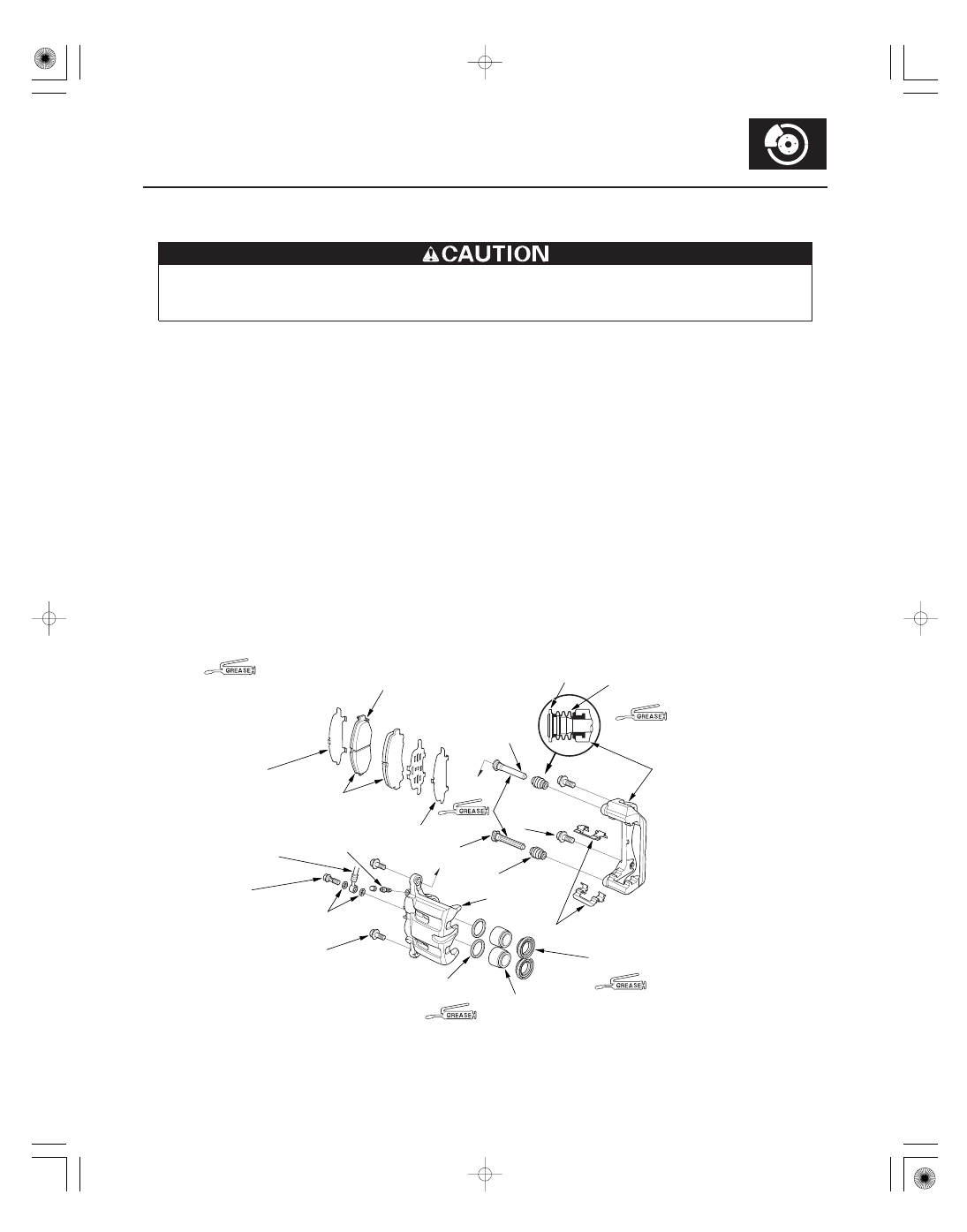
Front Brake Caliper Overhaul

CALIPER
BRACKET

CALIPER PIN

OUTER PAD SHIM C

WEAR INDICATOR

INNER PAD SHIM A

BRAKE
HOSE

BANJO BOLT
34 N·m
(3.5 kgf·m,
25 lbf·ft)

SEALING WASHERS

10 x 1.25 mm
72 N·m
(7.3 kgf·m, 53 lbf·ft)

BLEED SCREW
10 x 1.0 mm
8 N·m
(0.8 kgf·m, 6 lbf·ft)

LOWER
CALIPER PIN

PAD RETAINERS

PISTON BOOT

PISTON

PISTON SEAL

PIN BOOT

14 x 1.5 mm
137 N·m
(14.0 kgf·m,
101 lbf·ft)

CALIPER
BODY

: Honda silicone grease (P/N 08C30-B0234M)

BRAKE PADS

UPPER
CALIPER PIN

PIN BOOT

Frequent inhalation of brake pad dust, regardless of material composition, could be hazardous to your health.

• Avoid breathing dust particles.
• Never use an air hose or brush to clean brake assemblies. Use an OSHA-approved vacuum cleaner.

Remove, disassemble, inspect, reassemble, and install the caliper, and note these items:

NOTE: Make sure that the caliper pins are installed correctly.
The upper and lower caliper pins are different. If the caliper pins are installed in the wrong location, it will cause
uneven tire wear, vibration, and or uneven or rapid pad wear.

• Do not spill brake fluid on the vehicle; it may damage the paint; if brake fluid gets on the paint, wash it off

immediately with water.

• To prevent dripping brake fluid, cover disconnected hose joints with rags or shop towels.
• Clean all parts in brake fluid and air dry; blow out all passages with compressed air.
• Before reassembling, check that all parts are free of dirt and other foreign particles.
• Replace parts with new ones as specified in the illustration.
• Make sure no dirt or other foreign matter gets in the brake fluid.
• Make sure no grease or oil gets on the brake discs or pads.
• When reusing brake pads, always reinstall them in their original positions to prevent loss of braking efficiency.
• Do not reuse drained brake fluid. Use only clean Honda DOT 3 Brake Fluid from an unopened container. Using a

non-Honda brake fluid can cause corrosion and shorten the life of the system.

• Do not mix different brands of brake fluid as they may not be compatible.
• Coat the pistons, piston seal grooves, and caliper bores with clean brake fluid.
• Replace all rubber parts with new ones whenever disassembled.
• After installing the caliper, check the brake hose and line for leaks, interference, and twisting.

Install inner brake pad with
its wear indicator upward.

Replace.

Replace.

Replace.

Replace.

01

SJC8A00D14300014781KBAT00

01

SJC8A00D14300014781MAAT00

19-18

19-18

Conventional Brake Components

Master Cylinder Replacement

Master Cylinder Inspection

A

B

C

F

G

D
14 x 1.25 mm
35 N·m
(3.6 kgf·m,
26 lbf·ft)

E
8 x 1.25 mm
25 N·m
(2.5 kgf·m,
18 lbf·ft)

RESERVOIR CAP

RESERVOIR SEAL

STRAINER

RESERVOIR

GROMMETS

MASTER CYLINDER

SCREW

SEAL

• Do not spill brake fluid on the vehicle; it may

damage the paint; if brake fluid gets on the paint,
wash it off immediately with water.

• Be careful no to damage or deform the brake

lines during removal and inspection.

• To prevent the brake fluid from flowing, plug and

cover the hose ends and joints with a shop towel
or equivalent.

1. Remove the intake manifold cover.

2. Remove the intake air duct (see step 9 on page 5-2).

3. Disconnect the brake fluid level switch connectors

(A), and remove the reservoir cap (B).

4. Remove the brake fluid from the master cylinder

reservoir (C) with a syringe.

5. Disconnect the brake lines (D) from the master

cylinder. To prevent spills, cover the hose joints
with rags or shop towels.

6. Remove the master cylinder mounting nuts (E).

7. Remove the master cylinder (F) from the brake

booster (G). Be careful not to bend or damage the
brake lines when removing the master cylinder.

8. Install the master cylinder in the reverse order of

removal, and note this item: Spin the wheels to
check for brake drag.

9. Bleed the brake system (see page 19-9).

NOTE:

• Before reassembling, check that all parts are free of

dirt and other foreign particles.

• Do not try to disassemble the master cylinder

assembly. Replace the master cylinder assembly with
a new part if necessary.

• Do not allow dirt or foreign matter to contaminate the

brake fluid.

• Bleed the brake system (see page 19-9).

Check for blockage
of vent holes.

Check for damage
and deterioration.

Remove accumulated
sediment.

Check for damage.

Check for damage
and deterioration.

Check for leaks,
rust, and damage.

Check for damage
and deterioration.

01

SJC8A00D14300014701FEAT00

Functional Test

Leak Test

19-19

Brake Booster Test

B

A

1. With the engine stopped, press the brake pedal

several times to deplete the vacuum reservoir, then
press the brake pedal hard, and hold it for
15 seconds. If the brake pedal sinks, either the
master cylinder is bypassing brake fluid internally,
or the brake system (master cylinder, lines,
modulator, or caliper) is leaking.

2. Start the engine with the brake pedal pressed. If the

brake pedal sinks slightly, the vacuum booster is
operating normally. If the brake pedal height does
not vary, perform the leak test.

3. With the engine running, press the brake pedal

lightly, and shift the transmission to the D position.
Apply just enough pressure to hold back automatic
transmission creep. If the brake pedal sinks more
than 10 mm (3/8 in.) in 3 minutes, the master
cylinder is faulty. A slight change in pedal height
when the A/C compressor cycles on and off is
normal. (The A/C compressor load changes the
vacuum available to the booster.)

1. Press the brake pedal with the engine running, then

stop the engine. If the brake pedal height does not
vary while pressed for 30 seconds, the vacuum
booster is OK. If the pedal height rises go to step 6.
If it does not rise go to step 2.

2. Start the engine and let it idle for 30 seconds. Turn

the engine off, and wait 30 seconds. Press the
brake pedal several times using normal pressure.
When the pedal is first pressed, it should be low.
On consecutive applications, the pedal height
should gradually rise. Does the pedal rise on each
consecutive application? If it rises the booster is OK.
If it does not go to step 3.

3. Disconnect the brake booster vacuum hose (A) at

the booster. The check valve (B) is built into the
hose.

4. Start the engine, and let it idle. There should be

vacuum available. If no vacuum is available, the
check valve is not working properly. Replace the
brake booster vacuum hose and check valve, and
retest. If vacuum is found, go to step 5.

5. Reconnect the vacuum hose to the brake booster.

6. Start the engine, and then pinch the brake booster

vacuum hose between the check valve and the
booster.

7. Turn the engine off and wait 30 seconds. Press the

brake pedal several times using normal pressure.
When the pedal is first pressed, it should be low.
On consecutive applications, the pedal height
should gradually rise.

• If the pedal position does not vary inspect the

seal between the master cylinder and booster. If
the seal is OK, replace the brake booster.

• If the pedal position varies, replace the brake

booster vacuum hose/check valve assembly.

01

02

03

SJC8A00D14300014701KBAT00

19-20

Conventional Brake Components

Brake Booster Replacement

A

B

B

A

C
8 x 1.25 mm
25 N·m (2.5 kgf·m, 18 lbf·ft)

A

1. Remove the master cylinder (see page 19-18).

2. Disconnect the brake booster vacuum hose (A)

from the brake booster (B).

3. Remove the lock pin (A) and joint pin (B).

4. Remove the brake booster mounting nuts (C).

5. Pull the brake booster (A) forward, and remove it

from the engine compartment.

• Be careful not to damage the booster

surfaces and threads of the booster stud
bolts.

• Be careful not to bend or damage the

brake lines.

6. Install the brake booster in the reverse order of

removal, and note these items:

• Use a new lock pin whenever installing.
• After installing the brake booster and master

cylinder, fill the reservoir with new brake fluid,
bleed the brake system (see page 19-9), and
adjust the brake pedal height and free play
(see page 19-6).


Content   ..  318  319  320  321   ..