Honda Ridgeline. Manual - part 318
01
02
03
04
SJC8A00D14300000000LBAT00
Front
Rear
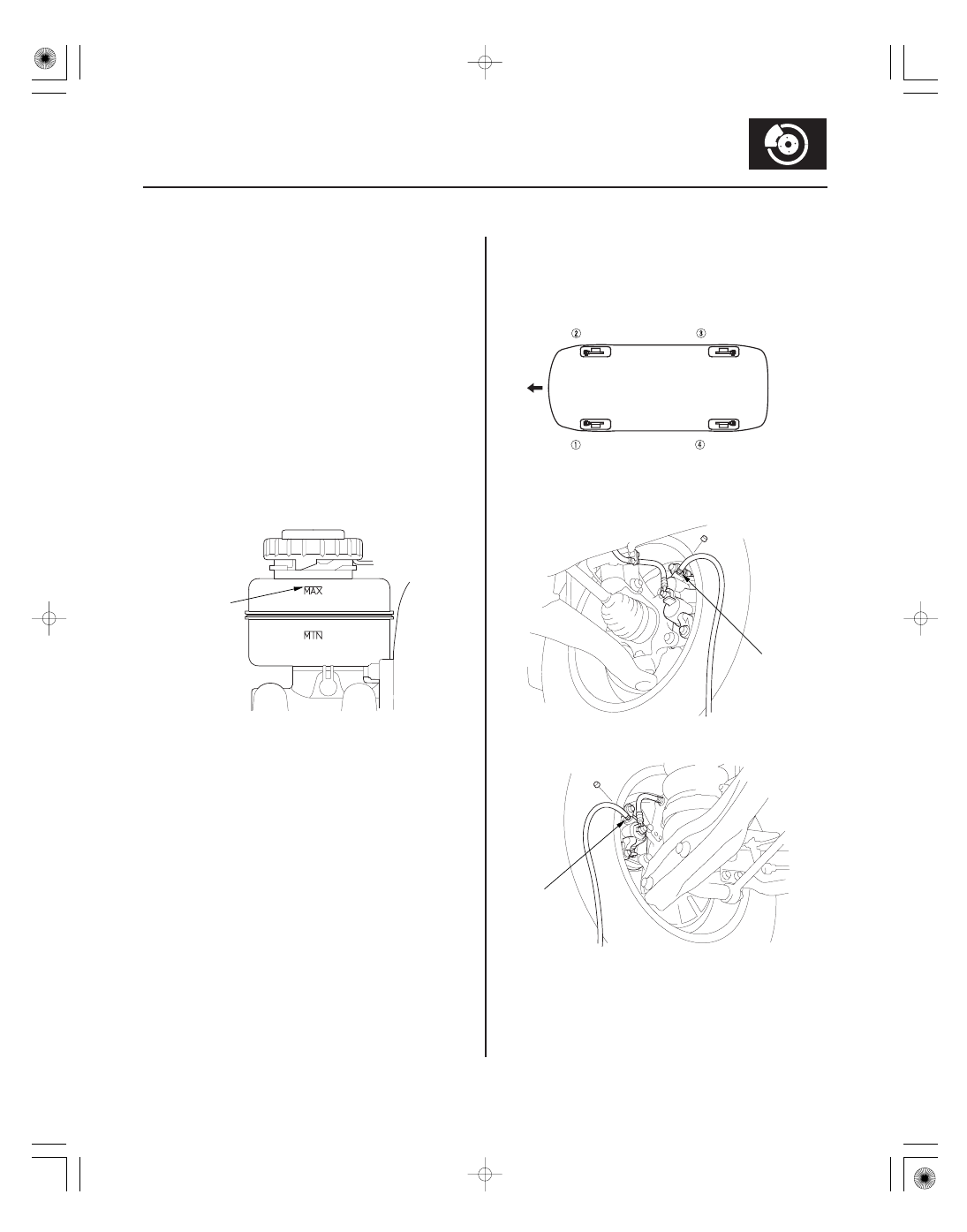
19-9
Brake System Bleeding
A
Front Right
Front Left
Rear Right
Rear Left
BLEEDING SEQUENCE:
9.0 N·m
(0.9 kgf·m,
7.0 lbf·ft)
9.0 N·m
(0.9 kgf·m,
7.0 lbf·ft)
NOTE:
• Do not reuse the drained fluid. Use only clean Honda
DOT 3 Brake Fluid from an unopened container.
Using a non-Honda brake fluid can cause corrosion
and shorten the life of the system.
• Do not mix different brands of brake fluid; they may
not be compatible.
• Make sure no dirt or other foreign matter is allowed
to contaminate the brake fluid.
• Do not spill brake fluid on the vehicle, it may damage
the paint; if brake fluid does contact the paint, wash it
off immediately with water.
• The reservoir on the master cylinder must be at the
MAX (upper) level mark at the start of the bleeding
procedure and checked after bleeding each brake
caliper. Add fluid as required.
1. Make sure the brake fluid level in the reservoir is at
the MAX (upper) level line (A).
2. Have someone slowly pump the brake pedal
several times, then apply steady pressure.
3. Starting at the left-front, loosen the brake bleed
screw to allow air to escape from the system. Then
tighten the bleed screw securely.
4. Repeat the procedure for each caliper until no air
bubbles are in the fluid. Bleed the calipers in the
sequence shown.
5. Refill the master cylinder reservoir to the MAX
(upper) level line.