Honda Ridgeline. Manual - part 308
04
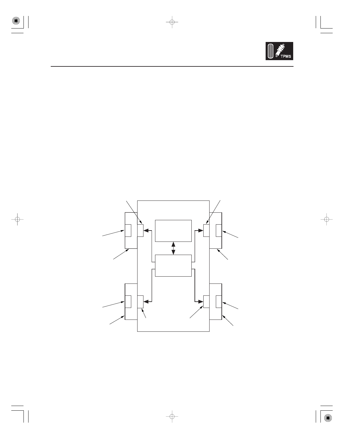
System Structure
Initiators
Control unit
Indicators
18-57
Vehicle
Initiator
(low frequency)
Initiator
(low frequency)
Gauge Control Module
6 Indicators
(LED drive)
Control Unit
(with radio
frequency antenna)
Initiator
(low frequency)
Initiator
(low frequency)
Tire Pressure Sensor
(sensor-transmitter)
Tire Pressure Sensor
(sensor-transmitter)
Wheel
(TPMS type)
Wheel
(TPMS type)
Tire Pressure Sensor
(sensor-transmitter)
Wheel
(TPMS type)
Tire Pressure Sensor
(sensor-transmitter)
Wheel
(TPMS type)
Whenever the engine is running, the TPMS control unit continuously monitors all four tires and the system. If it detects
low pressure in a tire, it alerts the driver by turning on the low pressure indicator and the appropriate tire indicator. If it
detects a problem in the system, it turns on the TPMS indicator.
Mounted on each wheel well, each initiator sends a start/stop signal to the tire pressure sensor in the tire below it.
Mounted in the lower dash on the driver’s side, the control unit sends signals to the initiators and receives signals
from them to verify the pressure sensor IDs every time the engine starts. It also receives signals from the transmitters
in the tire pressure sensors, and it continuously monitors and controls the system.
Six indicators are in the gauge control module: The low tire pressure indicator, four tire indicators to show which tire
is affected, and the TPMS indicator that comes on only if there’s a problem with the system. When two or more tire
pressures are low, the low tire pressure indicator comes on about 5 seconds before the appropriate tire indicator.
Once low pressure is detected, the system scans all four pressure sensors to ensure that it turns on the correct tire
indicator.
(cont’d)