Honda Ridgeline. Manual - part 301


  Index      Honda     Honda Ridgeline - service repair manual 2006-2008 year


Search            


Content   ..  299  300  301  302   ..


Honda Ridgeline. Manual - part 301


02

03

04

05

Special Tools Required

Knuckle/Hub Replacement

18-29

A
127 N·m
(13.0 kgf·m,
94 lbf·ft)

A

B

A
6 x 1.0 mm
9.8 N·m
(1.0 kgf·m,
7.2 lbf·ft)

B
12 x 1.25 mm
108 N·m
(11.0 kgf·m,
79.6 lbf·ft)

C

6 x 1.0 mm
9.8 N·m
(1.0 kgf·m, 7.2 lbf·ft)

B

A

• Ball joint remover, 28 mm 07MAC-SL0A202
• Hub dis/assembly tool, 42 mm 07GAF-SD40100
• Attachment, 62 x 68 mm 07746-0010500
• Driver 07749-0010000
• Attachment, 96 mm 07948-SB00101
• Support base 07965-SD90100

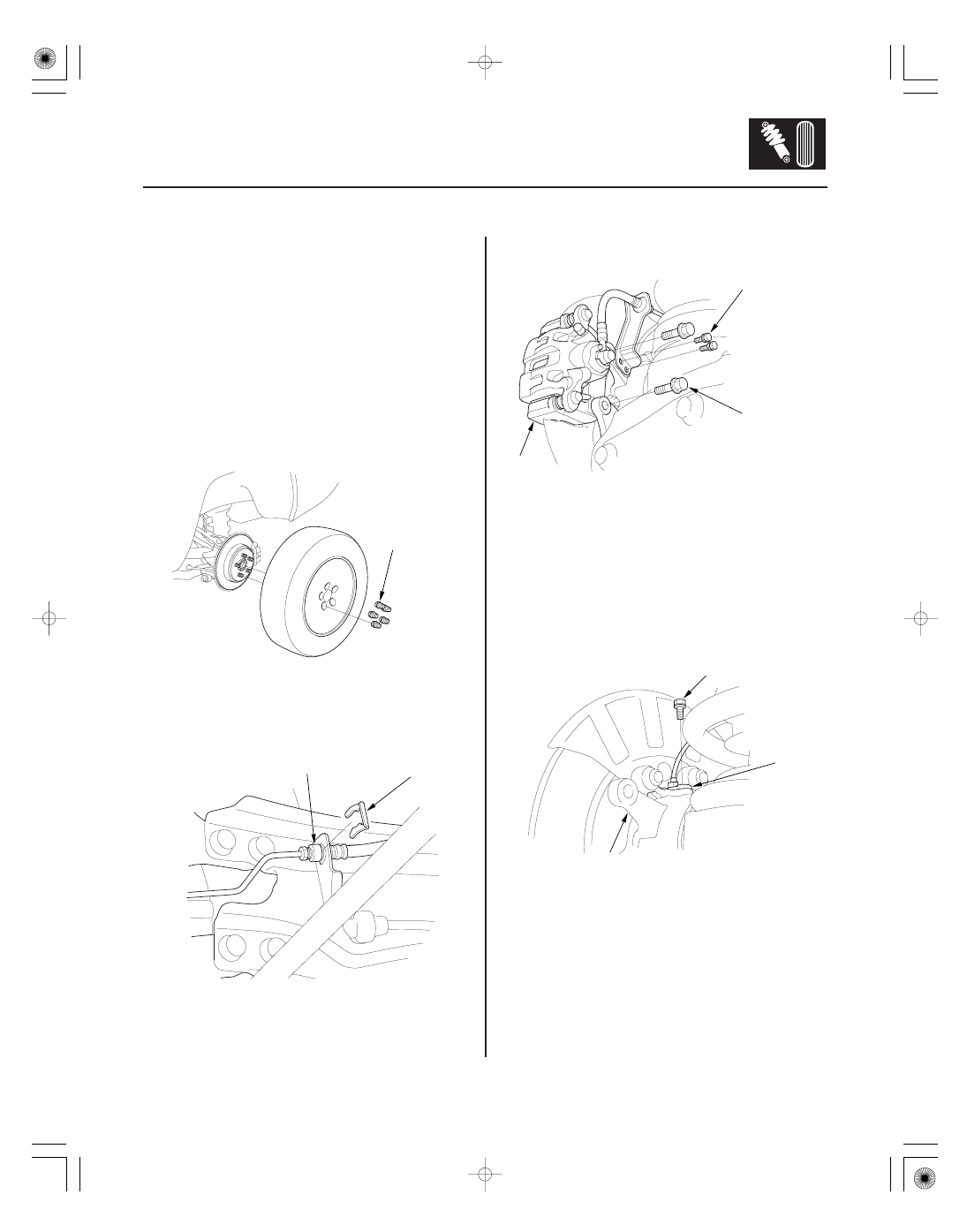
1. Raise the rear of the vehicle, and support it with

safety stands in the proper locations (see page
1-10).

2. Remove the wheel nuts (A) and rear wheel.

3. Remove and discard the brake hose clip (A) from

the brake hose (B).

NOTE: During installation, install the new brake
hose clip.

4. Remove the brake hose bracket mounting bolts (A)

from the knuckle.

5. Remove the brake caliper bracket mounting bolts

(B), and remove the caliper assembly (C) from the
knuckle. To prevent damage to the caliper
assembly or brake hose, use a short piece of wire
to hang the caliper assembly from the
undercarriage. Do not twist the brake hose with
force.

6. Remove the wheel sensor (A) from the knuckle (B).

Do not disconnect the wheel sensor connector.

(cont’d)

*02

08

*03

18-30

Rear Suspension

Knuckle/Hub/Wheel Bearing Replacement (cont’d)

B
24 x 1.5 mm
245 N·m
(25.0 kgf·m,
181 lbf·ft)

A

12 x 1.25 mm
49

59 N·m

(5.0

6.0 kgf·m,

36

43 lbf·ft)

07MAC-SL0A201

A

D
14 x 1.5 mm
93 N·m
(9.5 kgf·m, 69 lbf·ft)

B
14 x 1.5 mm
101 N·m
(10.3 kgf·m, 74.5 lbf·ft)

A

C

7. Raise the stake (A), then remove the spindle nut (B).

8. Remove the brake disc/drum (see page 19-24).

9. Check the rear hub for damage and cracks.

10. Remove the parking brake shoes (see page 19-28),

and parking brake cable (see page 19-35).

11. Remove the lock pin (A) from the upper arm ball

joint, then remove the nut.

NOTE: During installation, install the new lock pin
after tightening the nut.

12. Disconnect the upper arm ball joint from the

knuckle using the ball joint remover (see page
18-11).

13. Remove the flange nut (B), washer (C), and flange

bolt (D), then remove lower arm A.

NOTE: During installation, install the new flange
nut, new washer and new flange bolt.

Replace.

Replace.

*04

*05

18-31

A
12 x 1.25 mm
64 N·m
(6.5 kgf·m,
47 lbf·ft)

B

A
16 x 1.5 mm
142 N·m
(14.5 kgf·m,
105 lbf·ft)

C

E

D

B

14. Remove the flange bolts (A), and separate the

knuckle from the trailing arm (B).

NOTE: During installation, install the new flange
bolts.

15. Place a floor jack under lower arm B. Remove the

flange bolt (A).

NOTE: During installation, install the new flange
bolts.

16. Remove the driveshaft outboard joint (C) from the

knuckle (D) by tapping the driveshaft end (E) with a
plastic hammer while drawing the hub outward,
then remove the knuckle.

NOTE: Do not pull the driveshaft end outward. The
inner driveshaft joint may come apart.

17. Install the knuckle/hub in the reverse order of

removal, and note these items:

• Be careful not to damage the ball joint boot when

installing the knuckle.

• Tighten all mounting hardware to the specified

torque values.

• First install all the components and lightly tighten

the bolts and nuts, then raise the suspension to
load it with the vehicle’s weight before fully
tightening to the specified torque values.

• Torque the castle nut to the lower torque

specification, then tighten it only far enough to
align the slot with the ball joint pin hole. Do not
align the castle nut by loosening it.

• Use a new spindle nut on reassembly.
• Before installing the spindle nut, apply a small

amount of engine oil to the seating surface of the
nut. After tightening, use a drift to stake the
spindle nut shoulder against the driveshaft.

• Before installing the brake disc/drum, clean the

mating surface of the rear hub and the inside of
the brake disc/drum.

• Before installing the wheel, clean the mating

surface of the brake disc/drum and the inside of
the wheel.

• Check the wheel alignment, and adjust it if

necessary (see page 18-5).

(cont’d)

Replace.

Replace.

12

13

14

15

Wheel Bearing Replacement

18-32

Rear Suspension

Knuckle/Hub/Wheel Bearing Replacement (cont’d)

Press

07GAF-SD40100

A

B

C

C

Press

07GAF-SD40100

A

B

C

A

B

C

D

Press

07749-0010000

07746-0010500

A

B

1. Separate the hub (A) from the knuckle (B) using the

special tool and a hydraulic press. Hold the knuckle
with the attachment (C) of the hydraulic press or
equivalent tool. Be careful not to deform the
backing plate. Hold onto the hub to keep it from
falling when pressed clear.

2. Press the wheel bearing inner race (A) off of the

hub (B) using the special tool, a commercially
available bearing separator (C), and a press.

3. Remove the flange nuts (A), backing plate (B), and

snap ring (C) from the knuckle (D).

4. Press the wheel bearing (A) out of the knuckle (B)

using the special tools and a press.


Content   ..  299  300  301  302   ..