Honda Ridgeline. Manual - part 292


  Index      Honda     Honda Ridgeline - service repair manual 2006-2008 year


Search            


Content   ..  290  291  292  293   ..


Honda Ridgeline. Manual - part 292


49

50

51

52

17-51

(P/N 08798-9013)

A

B

A

B

A

B

2 mm
(0.08 in.)

A

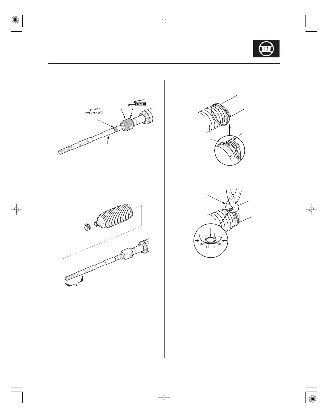
84. Apply multipurpose grease to the circumference of

the rack end joint housing (A).

85. Apply a light coat of silicone grease (P/N 08798-

9013) to the boot grooves (B) on the rack end.

86. Center the steering rack within its stroke. Install the

boots on the rack ends with the tie-rod clips. After
installing the boots, wipe the grease off the
threaded section (A) of the rack end.

87. Install the new boot bands by aligning the tabs (A)

with the holes (B) on the band.

88. Close the ear portion (A) of the band with

commercially available pincers Oetiker 1098 or
equivalent (B).

89. Slide the rack right and left to be certain that the

boots are not deformed or twisted.

90. Install the tie-rod ends.

91. Install the steering gearbox (see page 17-52).

01

02

03

04

SJC8A00F00000057111KCAT00

17-52

Power Steering

Steering Gearbox Installation

A

16 x 1.5 mm
28 N·m
(2.9 kgf·m,
21 lbf·ft)

B

A

B
16 x 1.5 mm
42 N·m
(4.3 kgf·m, 31 lbf·ft)

A

10 x 1.25 mm
38 N·m
(3.9 kgf·m, 28 lbf·ft)

10 x 1.25 mm
38 N·m
(3.9 kgf·m,
28 lbf·ft)

A

1. Install the pinion shaft grommet (A) on the valve

housing.

NOTE: If the return line (B) is removed, install it.

2. Slide the steering gearbox (A) between the front

subframe and body from the driver’s side. Place the
gearbox in position on the front subframe.

3. Connect the feed line (A), and tighten the 16 mm

flare nut (B) to the specified torque.

4. Install the gearbox stiffener bracket (A) on the front

subframe, and tighten the bolts and nut to the
specified torque.

*01

06

07

08

17-53

10 x 1.25 mm
58 N·m
(5.9 kgf·m, 43 lbf·ft)

A

B

FRONT

C
10 x 1.25 mm
39 N·m
(4.0 kgf·m, 29 lbf·ft)

B
6 x 1.0 mm
3 N·m
(0.3 kgf·m, 2 lbf·ft)

A

A

A

6 x 1.0 mm
9.8 N·m
(1.0 kgf·m, 7.2 lbf·ft)

5. Loosely install the new 10 mm flange bolts on the

left side of the gearbox.

6. Install the mounting cushion (A) on the right side of

the gearbox.

7. Install the mounting bracket (B) over the mounting

cushion, then install the two 10 mm flange bolts (C).
Tighten the four 10 mm flange bolts for the
gearbox to the specified torque.

8. Connect the return hose (A) securely, and tighten

the adjustable hose clamp (B) (see page 17-13).

9. Install the P/S line mounting brackets (A) on the

front suspension subframe and gearbox mounting
bracket.

(cont’d)

Replace.

*02

10

11

12

17-54

Power Steering

Steering Gearbox Installation (cont’d)

A

B
12 x 1.25 mm
117 N·m
(11.9 kgf·m,
86.1 lbf·ft)

C
14 x 1.5 mm
103 N·m
(10.5 kgf·m,
75.9 lbf·ft)

F
10 x 1.25 mm
38 N·m
(3.9 kgf·m,
28 lbf·ft)

E
10 x 1.25 mm
38 N·m
(3.9 kgf·m,
28 lbf·ft)

D

B
12 x 1.25 mm
74 N·m
(7.5 kgf·m, 54 lbf·ft)

C
14 x 1.5 mm
103 N·m
(10.5 kgf·m, 75.9 lbf·ft)

A

A

A

8 x 1.25 mm
22 N·m
(2.2 kgf·m, 16 lbf·ft)

10. Carefully raise the front subframe with the special

tool and the transmission jack or the powertrain lift
until the subframe is in position (see page 20-192).

11. Install the front subframe rear brackets (A). Tighten

the 12 mm flange bolts (B) and the new 14 mm
special bolts (C) on the right and the left of the
vehicle to the specified torque. For ’07-08 models:
Install the subframe bolt retainers (D). Tighten the
two flange bolts (E) and nuts (F) to the specified
torque.

12. Install the front subframe front brackets (A) with

12 mm flange bolts (B) and 14 mm special bolts (C),
and tighten to the specified torque.

13. Lower the front subframe supporting the

transmission jack or the powertrain lift.

14. Install the front splash shield (A) (see page 20-179).

15. Install the propeller shaft protector (A).

Replace.


Content   ..  290  291  292  293   ..