Honda Ridgeline. Manual - part 285


  Index      Honda     Honda Ridgeline - service repair manual 2006-2008 year


Search            


Content   ..  283  284  285  286   ..


Honda Ridgeline. Manual - part 285


01

02

03

SJC8A00F00000057161KCAT00

17-23

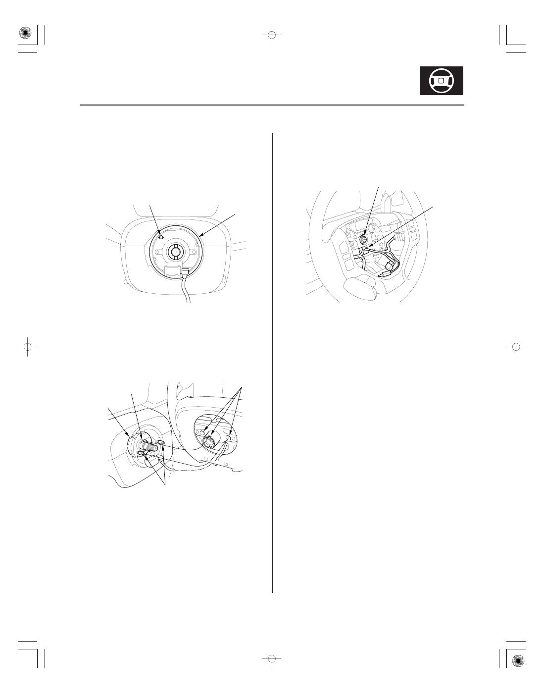
Steering Wheel Installation

A

B

A

B

C

D

A
49 N·m (5.0 kgf·m, 36 lbf·ft)

B

1. Before installing the steering wheel, make sure the

front wheels are aligned straight ahead, then center
the cable reel (A). Do this by first rotating the cable
reel clockwise until it stops. Then rotate it
counterclockwise about three full turns. The arrow
mark (B) on the cable reel label should point
straight up.

2. Position the two tabs (A) of the turn signal

canceling sleeve (B) as shown. Install the steering
wheel on to the steering column shaft, making sure
the steering wheel hub (C) engages the pins (D) of
the cable reel and tabs of the turn signal canceling
sleeve. Do not tap on the steering wheel or steering
column shaft when installing the steering wheel.

3. Install the steering wheel nut (A) and tighten it to

the specified torque. Connect the cable reel
subharness connector (B). Make sure the wire
harness is routed and fastened properly.

4. Install the driver’s airbag, and confirm that the

system is operating properly (see page 24-174).

5. Reconnect the negative cable to the battery and do

the following items:

• Turn the ignition switch ON (II); the SRS indicator

should come on for about 6 seconds and then go
off.

• Enter the anti-theft codes for the audio system

and the navigation system (If equipped).

• Set the clock (or vehicles without navigation).
• Verify cruise control, audio remote, voice control

and turn signal switch operation.

• Make sure the steering wheel is centered.

01

02

SJC8A00F00000057101KDAT00

Removal

17-24

Power Steering

Steering Column Removal and Installation

A

B

FULL STROKE: 34 mm (1.3 in.)

8 mm (0.31 in.)

MAXIMUM LOWER
POSITION

MAXIMUM UPPER
POSITION

A
NEUTRAL
POSITION

SRS components are located in this area. Review the
SRS component locations (see page 24-14) and the
precautions and procedures (see page 24-16) before
doing repairs or service.

1. Make sure you have the anti-theft codes for the

audio system and the navigation system (If
equipped).

2. Disconnect the negative cable from the battery.

3. Remove the driver’s airbag assembly and the

steering wheel (see page 17-21).

4. Remove the steering joint cover A.

5. Set the column shaft (A) in the neutral position by

pulling up the steering column to the uppermost
position, then lower it 8 mm (0.31 in.). Tighten the
lock lever (B).

03

17-25

A

B

C

D

16 N·m
(1.6 kgf·m, 12 lbf·ft)

22 N·m
(2.2 kgf·m, 16 lbf·ft)

22 N·m
(2.2 kgf·m, 16 lbf·ft)

A

E

F

6. Remove the column covers (A).

7. Move the shift lever (B) to the N position, and remove the shift cable from the column (see page 14-261), then set it

aside.

8. Remove the combination switch assembly (C) from the steering column shaft by removing the three mounting

screws, and disconnecting the connectors.

9. Disconnect the ignition switch connector and disconnect the harness clips.

10. Disconnect the immobilizer receiver unit, the park pin switch, and the shift lock solenoid.

11. Disconnect the steering joint (D), and remove it from the column shaft.

12. Remove the steering column (E) by removing the attaching nuts and bolts.

13. Remove the center guide (F) (if equipped) from the top of the pinion shaft, and discard it. The center guide is for

factory assembly use only.

(cont’d)

04

05

06

±

Installation

17-26

Power Steering

Steering Column Removal and Installation (cont’d)

A

B

C

D

28 °

20 °

FRONT

B

C
22 N·m
(2.2 kgf·m, 16 lbf·ft)

D
22 N·m
(2.2 kgf·m,
16 lbf·ft)

A

A

1. Install the steering column in the reverse order of

removal, and note these items:

• Take care not to let the sliding plates fall out of

position during column installation.

• Make sure the wires are not caught or pinched by

any parts.

2. Center the steering rack within its stroke.

3. Insert the upper end of the steering joint onto the

steering shaft (A) (line up the bolt hole (B) with the
flat portion (C) on the shaft), and loosely install the
upper joint bolt.

4. Slip the lower end of the steering joint onto the

pinion shaft taking care to align the gap (D) within
the angle.

5. Align the bolt hole (A) on the steering joint with the

groove (B) around the pinion shaft then loosely
install the lower joint bolt (C).

6. Pull on the steering joint to make sure that the

steering joint is fully seated, then tighten the lower
joint bolt to the specified torque.

7. Tighten the upper joint bolt (D) to the specified

torque.

8. Install the steering joint cover A.

9. Install the steering wheel (see page 17-23).

10. Reconnect the negative battery cable to the battery,

and do these tasks:

• Turn the ignition switch ON (II); the SRS indicator

should come on for about 6 seconds and then go
off.

• Enter the anti-theft codes for the audio system

and the navigation system (if equipped).

• Set the clock (or vehicles without navigation).
• Make sure the horn and turn signal switches

work properly.

• Make sure the steering wheel switches work

properly.

• Make sure the steering wheel is centered.


Content   ..  283  284  285  286   ..