Honda Ridgeline. Manual - part 276
01
SJC8A00E16266500000LDAT00
Exploded View
16-30
Driveline/Axle
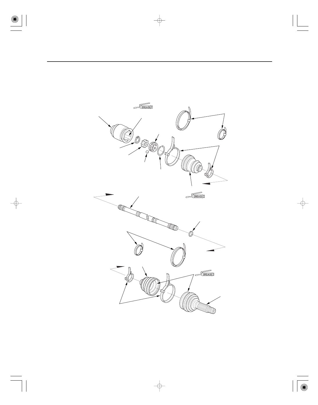
Rear Driveshaft Reassembly
INBOARD JOINT
BEARING RACE
SNAP RING
STEEL BALL
BEARING RETAINER
DRIVESHAFT
INBOARD BOOT
OUTBOARD BOOT
OUTBOARD JOINT
DOUBLE LOOP BANDS
LOCKING TAB BANDS
CIRCLIP
DOUBLE LOOP BANDS
LOCKING TAB BANDS
CIRCLIP
Use the grease included
in the inboard boot set.
Replace.
(Boot band replacement only.)
Replace.
Replace.
Use the grease included
in the inboard boot set.
Use the grease included
in the outboard boot set.
Replace.
(Boot band replacement only.)
Replace.
Replace.