Honda Ridgeline. Manual - part 262


  Index      Honda     Honda Ridgeline - service repair manual 2006-2008 year


Search            


Content   ..  260  261  262  263   ..


Honda Ridgeline. Manual - part 262


02

03

01

SJC8A00K80200081441FAAT00

YES

NO

YES

NO

YES

NO

DTC 44-1:

15-30

15-30

Rear Differential

DTC Troubleshooting (cont’d)

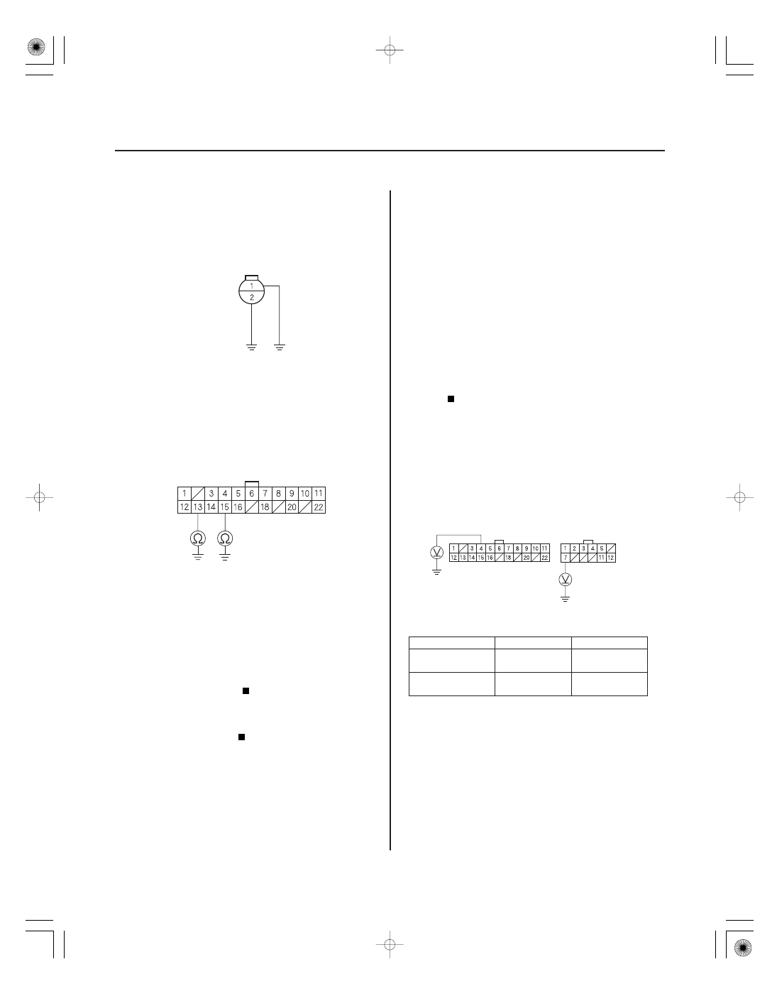
DIFFERENTIAL OIL TEMPERATURE
SENSOR 2P CONNECTOR

JUMPER WIRE

VTM-4 CONTROL UNIT CONNECTOR A (22P)

TOH (WHT)

TOL (BLK)

VTM-4 CONTROL UNIT CONNECTORS

PWR (RED/BLU)

FSR (ORN/GRN)

A (22P)

B (12P)

12. Connect the differential oil temperature sensor 2P

connector terminals to body ground with jumper
wires.

13. Check for continuity between the No. 13 and No. 15

terminals of the VTM-4 control unit connector A
(22P) and body ground.

Check for poor connections or loose

terminals at the VTM-4 control unit and the
differential oil temperature sensor connectors. If
the connections are OK, replace the VTM-4 control
unit (see page 15-50).

Repair open in the wire between the VTM-4

control unit (A13 or A15) and the differential oil
temperature sensor.

NOTE: Before you troubleshoot, review the general
troubleshooting information (see page 15-4).

1. Turn the ignition switch ON (II).

2. Clear the DTC (see page 15-8).

3. Test-drive the vehicle, and check for DTCs with the

HDS.

Go to step 4.

Intermittent failure, the system is OK at this

time.

4. Measure voltage between the No. 4 terminal of the

VTM-4 control unit connector A (22P) and body
ground, and between the No. 7 terminal of the
VTM-4 control unit connector B (12P) and body
ground with the ignition switch ON (II), and with the
engine started.

Condition

B7 (PWR)

A4 (FSR)

Ignition switch

ON (II)

Less than 3 V

Battery

voltage

Engine start

Battery

voltage

Less than 1 V

Go to step 16.

Go to step 5.

5. Turn the ignition switch OFF.

VTM-4 Relay

Terminal side of female terminals

Wire side of female terminals

Wire side of female terminals

Is ther e continuity?

Is DT C 44-1 indicated?

Is the voltage cor r ect?

01

03

04

YES

NO

YES

NO

YES

NO

YES

NO

15-31

VTM-4 RELAY 5P CONNECTOR

BLK/YEL

WHT/RED

PWR (RED/BLU)

FSR (ORN/GRN)

VTM-4 CONTROL UNIT CONNECTORS

A (22P)

B (12P)

PWR (RED/BLU)

FSR (ORN/GRN)

VTM-4 CONTROL UNIT CONNECTORS

A (22P)

B (12P)

6. Remove the VTM-4 relay, and test it (see page

22-75).

Go to step 7.

Replace the VTM-4 relay (see page 15-50).

7. Turn the ignition switch ON (II) with the VTM-4

relay removed.

8. Measure voltage between the No. 1 and No. 5

terminals of the VTM-4 relay 5P connector and
body ground.

Go to step 9.

Check for blown No. 4 (20 A) fuse in the

auxiliary fuse box or No. 18 (15 A) fuse in the
driver’s under-dash fuse/relay box. If the fuses are
OK, repair open in the wire between the auxiliary
fuse box or the driver’s under-dash fuse/relay box
and the VTM-4 relay.

9. Turn the ignition switch OFF.

10. Disconnect the VTM-4 control unit connector A

(22P) and connector B (12P).

11. Turn the ignition switch ON (II).

12. Measure voltage between the No. 4 terminal of the

VTM-4 control unit connector A (22P) and body
ground, and between the No. 7 terminal of the
VTM-4 control unit connector B (12P) and body
ground.

Repair short to power in the wire between

the VTM-4 control unit (A4 or B7) and the VTM-4
relay.

Go to step 12.

13. Turn the ignition switch OFF.

14. Check for continuity between the No. 4 terminal of

the VTM-4 control unit connector A (22P) and body
grond, and between the No. 7 terminal of the
VTM-4 control unit connector B (12P) and body
ground.

Repair short to ground in the wire between

the VTM-4 control unit (A4 or B7) and the VTM-4
relay.

Go to step 15.

(cont’d)

Terminal side of female terminals

Wire side of female terminals

Wire side of female terminals

Is the V T M-4 r elay OK ?

Is ther e batter y voltage?

Is ther e batter y voltage?

Is ther e continuity?

02

01

SJC8A00K80200081511FAAT01

YES

NO

YES

NO

YES

NO

YES

NO

DTC 51-1, 52-1, 53-1, 53-2, 54-1:

15-32

15-32

Rear Differential

DTC Troubleshooting (cont’d)

PWR (RED/BLU)

VTM-4 CONTROL UNIT
CONNECTOR B (12P)

FSR (ORN/GRN)

VTM-4 RELAY CONNECTOR (5P)

RED/BLU

ORN/GRN

VTM-4 CONTROL UNIT
CONNECTOR A (22P)

LEFT CLUTCH ELECTROMAGNETIC COIL
2P CONNECTOR

15. Check for continuity between the No. 4 terminal of

the VTM-4 control unit connector A (22P) and the
No. 3 terminal of the VTM-4 relay, and between the
No. 7 terminal of the VTM-4 control unit connector
B (12P) and the No. 2 terminal of the VTM-4 relay.

Go to step 16.

Repair open in the wire between the A4 or B7

terminals of the VTM-4 control unit and the VTM-4
relay.

16. Check for poor connections or loose terminals at

the VTM-4 control unit and the VTM-4 relay
connectors. If the connections are OK, go to step
17.

17. Test-drive the vehicle, and check for DTCs with the

HDS.

Replace the VTM-4 control unit (see page

15-50).

The system is OK at this time.

NOTE: Before you troubleshoot, review the general
troubleshooting information (see page 15-4).

1. Turn the ignition switch ON (II).

2. Clear the DTC (see page 15-8).

3. Test-drive the vehicle, and check for DTCs with the

HDS.

Go to step 4.

Intermittent failure, the system is OK at this

time.

4. Turn the ignition switch OFF.

5. Disconnect the left clutch electromagnetic coil 2P

connector on the differential.

6. Measure resistance between the No. 1 and No. 2

terminals of the left clutch electromagnetic coil 2P
connector.

Go to step 7.

Replace the rear differential assembly.

Left Clutch

Electromagnetic Coil

Wire side of female terminals

Terminal side of male terminals

Is ther e continuity?

Is DT C 44-1 indicated?

Is DT Cs 51-1, 52-1, 53-2, and/ or 54-1 indicated?

Is ther e 1 to 3

?

02

03

04

YES

NO

YES

NO

YES

NO

15-33

LEFT CLUTCH ELECTROMAGNETIC COIL
2P CONNECTOR

VTM-4 CONTROL UNIT CONNECTOR B (12P)

LCOL
(BLK/WHT)

LCOH
(BLK/RED)

VTM-4 CONTROL UNIT CONNECTOR B (12P)

LCOL
(BLK/WHT)

LCOH
(BLK/RED)

7. Measure resistance between the No. 1 terminal of

the left clutch electromagnetic coil and differential
carrier assembly.

Go to step 8.

Replace the rear differential assembly.

8. Disconnect the VTM-4 control unit connector B

(12P).

9. Turn the ignition switch ON (II).

10. Measure voltage between the No. 1 and No. 2

terminals of the VTM-4 control unit connector B
(12P) and body ground.

Repair short to power in the wire between

the VTM-4 control unit (B1 or B2) and the left clutch
electromagnetic coil.

Go to step 11.

11. Turn the ignition switch OFF.

12. Check for continuity between the No. 1 and No. 2

terminals of the VTM-4 control unit connector B
(12P) and body ground.

Repair short to ground in the wire between

the VTM-4 control unit (B1 or B2) and the left clutch
electromagnetic coil.

Go to step 13.

(cont’d)

Terminal side of male terminals

Wire side of female terminals

Wire side of female terminals

Is ther e about 50 M

or mor e?

Is ther e batter y voltage?

Is ther e continuity?


Content   ..  260  261  262  263   ..