Honda Ridgeline. Manual - part 261
03
01
02
−
−
−
−
−
−
YES
NO
YES
NO
YES
NO
15-26
Rear Differential
DTC Troubleshooting (cont’d)
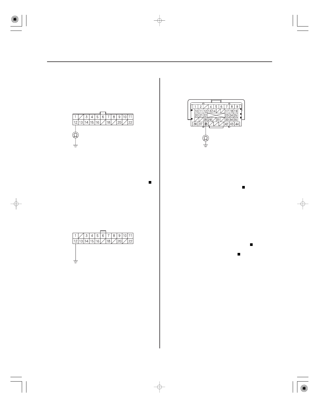
VTM-4 CONTROL UNIT CONNECTOR A (22P)
NEP (BLU)
VTM-4 CONTROL UNIT CONNECTOR A (22P)
NEP (BLU)
JUMPER WIRE
PCM CONNECTOR A (44P)
NEP (BLU)
15. Check for continuity between the No. 12 terminal of
the VTM-4 control unit connector A (22P) and body
ground.
Repair short to ground in the wire between
the VTM-4 control unit (A12), and the PCM (A28).
Go to step 16.
16. Connect the No. 12 terminal of the VTM-4 control
unit connector A (22P) to body ground with a
jumper wire.
17. Check for continuity between the No. 28 terminal of
the PCM connector A (44P) and body ground.
Go to step 18.
Repair open in the wire between the VTM-4
control unit (A12), and the PCM (A28).
18. Check for poor connections or loose terminals at
the VTM-4 control unit, and the PCM connectors. If
the connections are OK, replace the VTM-4 control
unit, then go to step 19.
19. Test-drive the vehicle, and watch the VTM-4
indicator.
Replace the PCM (see page 11-205).
The system is OK at this time.
Wire side of female terminals
Wire side of female terminals
Wire side of female terminals
Is ther e continuity?
Is ther e continuity?
Is DT Cs 37 -1 and/ or 38-1 indicated?