Honda Ridgeline. Manual - part 260
01
SJC8A00K80200081231FAAT01
−
−
−
−
−
−
−
−
DTC 23-1, 23-2, 24-1, 24-2:
YES
NO
YES
NO
YES
NO
YES
NO
15-22
Rear Differential
DTC Troubleshooting (cont’d)
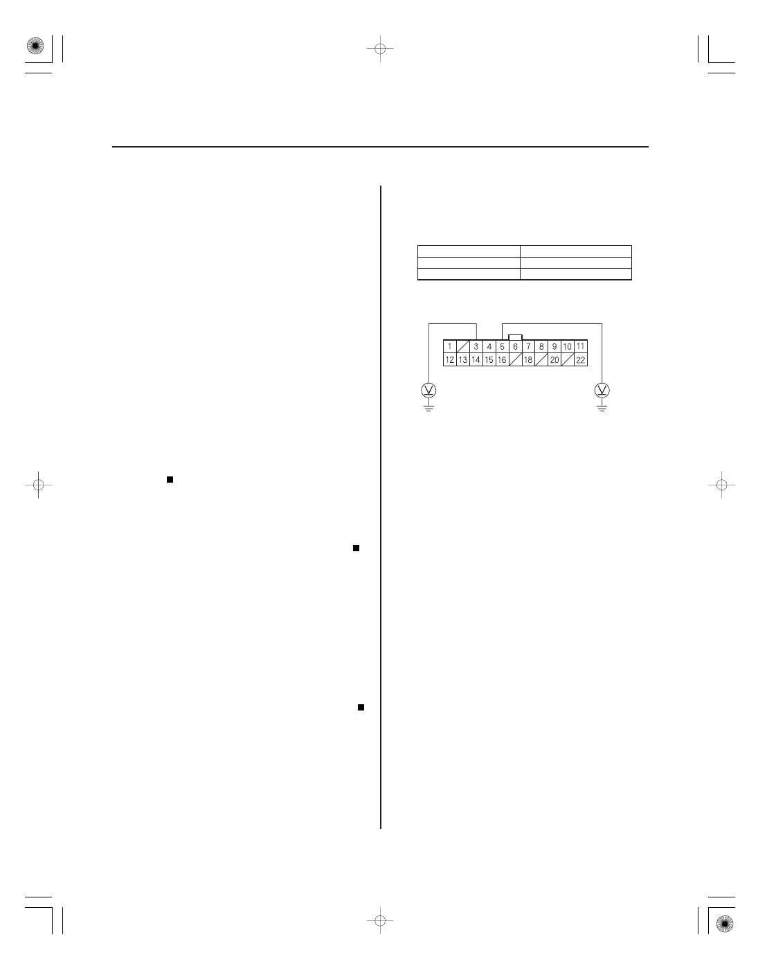
VTM-4 CONTROL UNIT CONNECTOR A (22P)
RLP (GRY/YEL)
RRP (GRY/RED)
Rear Wheel
Sensors
NOTE: Before you troubleshoot, review the general
troubleshooting information (see page 15-4).
1. Turn the ignition switch ON (II).
2. Clear the DTC (see page 15-8).
3. Start the engine, shift the transmission into D. Test-
drive the vehicle at speeds over 25 mph (40 km/h),
while keeping the engine speed below 2,500 rpm
for at least 30 seconds.
NOTE: Be careful not to overheat the rear
differential clutch system.
4. Check for DTSs with the HDS.
Go to step 5.
Intermittent failure, the system is OK at this
time.
5. Check for DTCs in the VSA system with the HDS.
Go to the indicated DTCs troubleshooting.
Go to step 6.
6. Turn the ignition switch OFF.
7. Raise the vehicle, and make sure it is securely
supported.
8. Spin the rear wheels by hand, and check for rear
brake drag.
Repair cause of rear brake drag, and retest.
Go to step 9.
9. Turn the ignition switch ON (II).
10. Measure voltage between the No. 3 and No. 5
terminals of the VTM-4 control unit connector A
(22P) and body ground while rotating the
appropriate wheel (1 rotation/second).
DTC
Appropriate Terminal
23 (Left-rear)
A5
24 (Right-rear)
A3
Go to step 18.
Go to step 11.
11. Turn the ignition switch OFF.
12. Disconnect the VTM-4 control unit connector A
(22P) and the VSA modulator-control unit 46P
connector.
Wire side of female terminals
Is DT Cs 23-1, 23-2, 24-1, and/ or 24-2 indicated?
Ar e ther e any V SA DT Cs indicated?
Ar e the r ear br akes dr agging?
Is ther e about 2 V to 3 V ?