Honda Ridgeline. Manual - part 242


  Index      Honda     Honda Ridgeline - service repair manual 2006-2008 year


Search            


Content   ..  240  241  242  243   ..


Honda Ridgeline. Manual - part 242


08

09

10

11

14-353

A

B

C

D

E

F

E

D

D

D

D

C

C

C

D

E

F

D

E

D

C

D

C

D

A

B

A

B

C

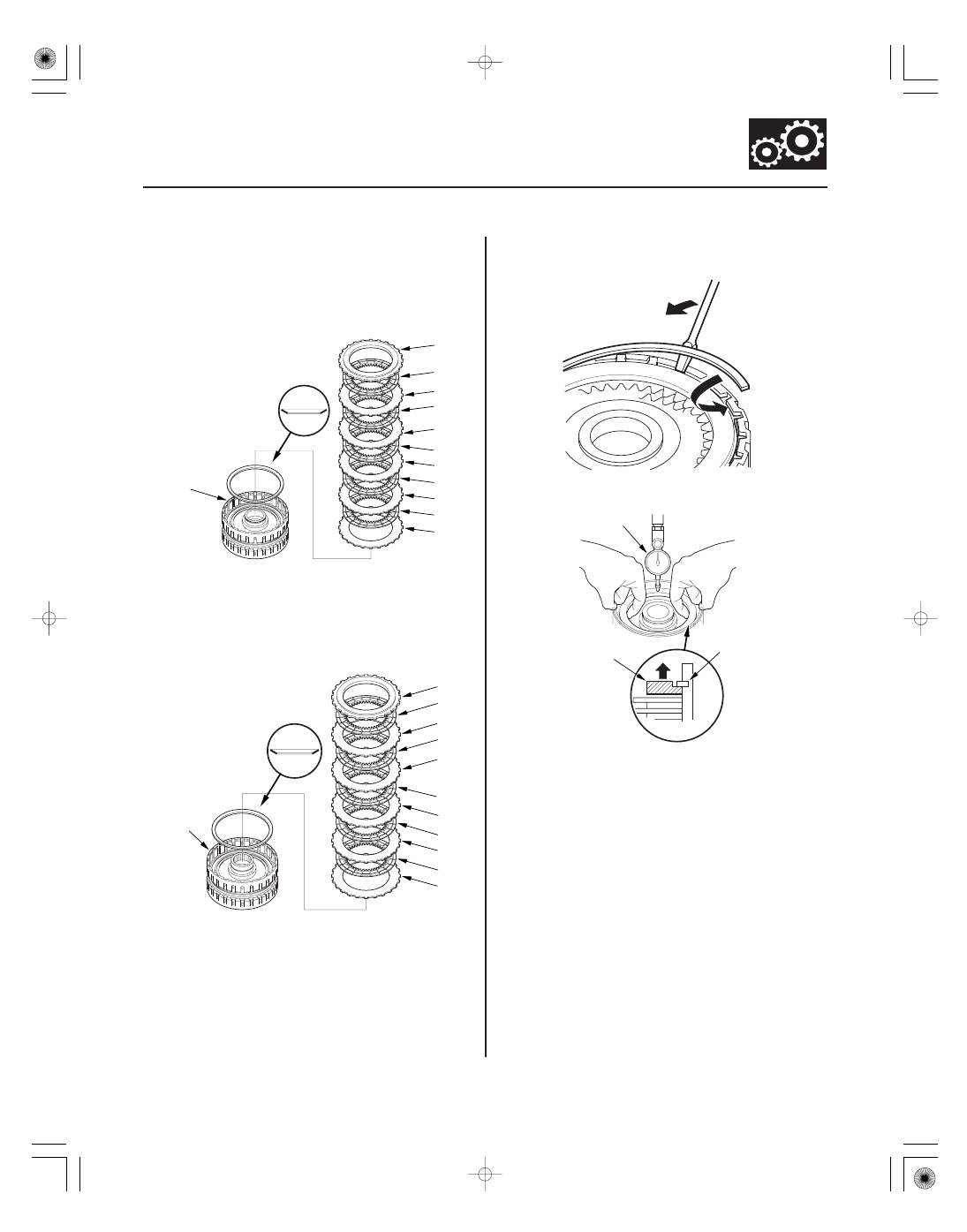
10. Install the disc spring (A) in the 4th clutch drum (B)

in the direction shown. Starting with the 4th clutch
flat-plate, alternately install the flat-plates (C) (3)
and discs (D) (3), and alternately install the wave-
plates (E) (2) and discs (D) (2). Install the clutch end-
plate (F) with the flat side down on the top disc.

11. Install the disc spring (A) in the 5th clutch drum (B)

in the direction shown. Starting with the 5th clutch
flat-plate, alternately install the flat-plates (C) (3)
and discs (D) (3), and alternately install the wave-
plates (E) (2) and discs (D) (2). Install the clutch end-
plate (F) with the flat side down on the top disc.

12. Install the snap ring with a screwdriver to secure

the clutch end-plate.

13. Set a dial indicator (A) on the clutch-end-plate (B).

14. Zero the dial indicator with the clutch end-plate

lifted up to the snap ring (C).

(cont’d)

12

13

Clearance between Clutch End-Plate and Top
Disc
Service Limit:
1st Clutch:

1.15

1.35 mm (0.045

0.053 in.)

2nd Clutch: 1.05

1.25 mm (0.041

0.049 in.)

3rd Clutch: 0.8

1.0 mm (0.031

0.039 in.)

4th Clutch: 0.75

0.95 mm (0.030

0.037 in.)

5th Clutch: 0.75

0.95 mm (0.030

0.037 in.)

1ST CLUTCH END-PLATES

Plate

No.

Part Number

Thickness

2ND CLUTCH END-PLATES

Plate

No.

Part Number

Thickness

14-354

Shafts and Clutches

Clutch Clearance Inspection (cont’d)

C

A

E

D

B

07ZAE-PRP0100

15. Release the clutch end-plate to lower the clutch-

end-plate, then put the clutch compressor
attachment on the end-plate (A).

16. Press the special tool down with 150

160 N

(15

16 kgf, 33

35 lbf) (B) using a force gauge, and

read the dial indicator (C).

17. The dial indicator reads the clearance (D) between

the clutch end-plate and top disc (E). Take
measurements in at least three places, and use the
average as the actual clearance.

18. If the clearance is out of the service limit, select a

new clutch-end-plate from the following table.

1

22551-RDK-003

3.1 mm (0.122 in.)

2

22552-RDK-003

3.2 mm (0.126 in.)

3

22553-RDK-003

3.3 mm (0.130 in.)

4

22554-RDK-003

3.4 mm (0.134 in.)

5

22555-RDK-003

3.5 mm (0.138 in.)

6

22556-RDK-003

3.6 mm (0.142 in.)

7

22557-RDK-003

3.7 mm (0.146 in.)

8

22558-RDK-003

3.8 mm (0.150 in.)

9

22559-RDK-003

3.9 mm (0.154 in.)

1

22561-RDK-003

2.1 mm (0.083 in.)

2

22562-RDK-003

2.2 mm (0.087 in.)

3

22563-RDK-003

2.3 mm (0.091 in.)

4

22564-RDK-003

2.4 mm (0.094 in.)

5

22565-RDK-003

2.5 mm (0.098 in.)

6

22566-RDK-003

2.6 mm (0.102 in.)

7

22567-RDK-003

2.7 mm (0.106 in.)

8

22568-RDK-003

2.8 mm (0.110 in.)

9

22569-RDK-003

2.9 mm (0.114 in.)

3RD CLUTCH END-PLATES

Plate

No.

Part Number

Thickness

4TH and 5TH CLUTCH END-PLATES

Plate

No.

Part Number

Thickness

14-355

1

22591-RDK-A01

2.1 mm (0.083 in.)

2

22592-RDK-A01

2.2 mm (0.087 in.)

3

22593-RDK-A01

2.3 mm (0.091 in.)

4

22594-RDK-A01

2.4 mm (0.094 in.)

5

22595-RDK-A01

2.5 mm (0.098 in.)

6

22596-RDK-A01

2.6 mm (0.102 in.)

7

22597-RDK-A01

2.7 mm (0.106 in.)

8

22598-RDK-A01

2.8 mm (0.110 in.)

9

22599-RDK-A01

2.9 mm (0.114 in.)

1

22571-RJB-003

2.1 mm (0.083 in.)

2

22572-RJB-003

2.2 mm (0.087 in.)

3

22573-RJB-003

2.3 mm (0.091 in.)

4

22574-RJB-003

2.4 mm (0.094 in.)

5

22575-RJB-003

2.5 mm (0.098 in.)

6

22576-RJB-003

2.6 mm (0.102 in.)

7

22577-RJB-003

2.7 mm (0.106 in.)

8

22578-RJB-003

2.8 mm (0.110 in.)

9

22579-RJB-003

2.9 mm (0.114 in.)

19. Install the new clutch end-plate, and recheck the

clearance. If the thickest clutch end-plate is
installed, but the clearance is still over the service
limit, replace the clutch discs and plates.

01

02

03

SJC8A00E10411310011LDAT00

Special Tools Required

14-356

Shafts and Clutches

Clutch Reassembly

C

A

B

A

A

C

A

B

C

A

B

A

• Clutch spring compressor attachment

07LAE-PX40100 or 07HAE-PL50101

• Clutch spring compressor bolt assembly

07GAE-PG40200 or 07GAE-PG4020A

1. Soak the clutch discs thoroughly in ATF for a

minimum of 30 minutes.

2. Install the new O-rings (A) on the 1st-hold clutch

piston (B), and install the 1st-hold clutch piston in
the 1st clutch piston (C).

3. Install the new O-rings (A) on the 1st clutch piston

(B), and install the 1st/1st-hold clutch piston in the
1st/1st-hold clutch drum (C) while applying
pressure and rotating to ensure proper seating. Do
not pinch the O-rings.

4. Install the O-rings (A) on the 2nd, 3rd, 4th and 5th

clutch piston (B).

5. Install the clutch pistons in the clutch drums (C)

while applying pressure and rotating to ensure
proper seating. Do not pinch the O-ring.


Content   ..  240  241  242  243   ..