Honda Ridgeline. Manual - part 241
01
SJC8A00E10411310011MAAT00
Clutch Discs
Standard Thickness: 1.94 mm (0.076 in.)
Clutch Flat-plates and Clutch Wave-plates
Standard Thickness
1st Clutch:
1.6 mm (0.063 in.)
1st-hold Clutch: 1.8 mm (0.071 in.)
2nd Clutch:
1.8 mm (0.071 in.)
3rd Clutch:
2.0 mm (0.079 in.)
4th Clutch:
1.6 mm (0.063 in.)
5th Clutch:
1.6 mm (0.063 in.)
14-349
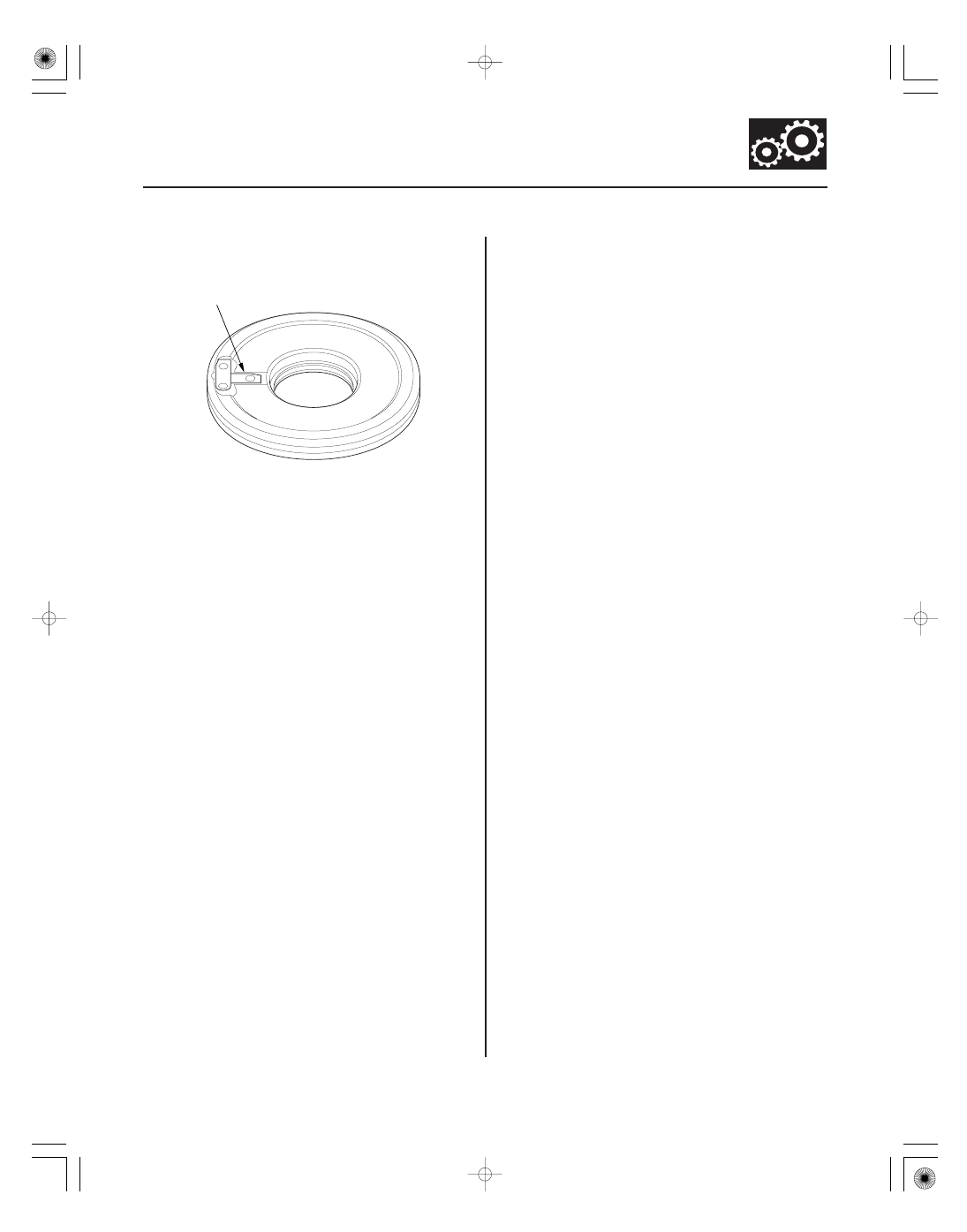
Clutch Inspection
A
1. Inspect the clutch pistons and the clutch piston
check valves (A).
2. If the clutch piston check valve is loose or damaged,
replace the clutch piston.
3. Check the spring retainer for wear and damage.
4. If the spring retainer is worn or damaged, replace it.
5. Inspect the clutch discs, clutch plates, and clutch
end plate for wear, damage, and discoloration.
6. If the clutch discs are worn or damaged, replace
them as a set. If the clutch discs are replaced,
inspect the clearance between the clutch end-plate
and the top disc.
7. If any plate is worn, damaged, or discolored,
replace the damaged plate with a new plate, and
inspect the other wave-plates for a phase
difference. If the clutch plate is replaced, inspect
the clearance between the clutch end-plate and the
top disc.
8. If the clutch end plate is worn, damaged, or
discolored, inspect the clearance between the
clutch end-plate and the top disc, then replace the
clutch end plate.