Honda Ridgeline. Manual - part 227


  Index      Honda     Honda Ridgeline - service repair manual 2006-2008 year


Search            


Content   ..  225  226  227  228   ..


Honda Ridgeline. Manual - part 227


02

03

04

14-293

07GAB-PF50101 or
07GAB-PF50100

C

A

B

A

C

B

6. Pry the lock tab of the lock washer (I) on the control

lever (J), and remove the nut, the lock washer, the
spring washer, and the control lever.

7. Pry the lock tabs of the lock washer (K) on the

transmission range switch (L), hold the selector
control shaft (M) with a 6.0 mm wrench, and loosen
the locknut (N).

8. Remove the locknut and the lock washer, then

remove the transmission range switch (two bolts).

9. Remove the output shaft (countershaft) speed

sensor (O) and the input shaft (mainshaft) speed
sensor (P).

10. Remove the ATF temperature sensor connector

from the connector bracket (Q) and the harness
clamp from clamp bracket, then remove the ATF
temperature sensor (R).

11. Remove the end cover (S) (three bolts), the snap

ring cap (T) (two bolts), the sealing plug (U), and
the washer (V).

12. Remove the line bolts (W), the ATF cooler lines (X),

and the sealing washers (Y).

13. Remove the 3rd clutch transmission fluid pressure

switch (Z) and the sealing washer.

14. Remove the 4th clutch transmission fluid pressure

switch (AA) and the sealing washer.

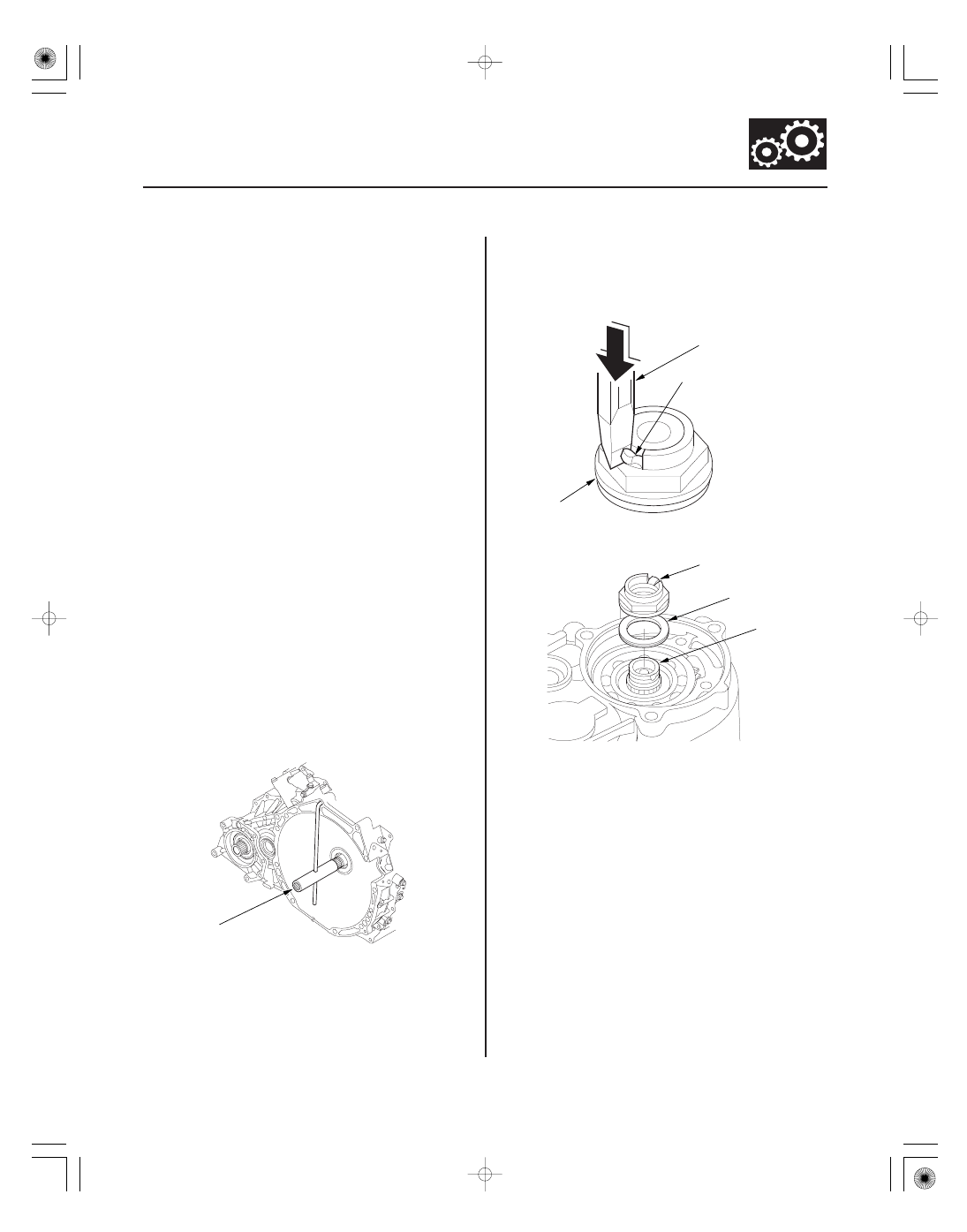
15. Slip the mainshaft holder onto the mainshaft.

16. Cut the lock tab (A) of the mainshaft locknut (B)

using a chisel (C).

NOTE: Keep all of the chiseled particles out of the
transmission.

17. Remove the locknut (A) from the mainshaft (B).

18. Pry the lock washer (C), and remove it.

(cont’d)

05

14-294

Automatic Transmission

Transmission Disassembly (cont’d)

A

B

C

D

E

F

G

H

I

J

K

L

M

N

O

P

Q

R

S

T

U

V

W

X

Y

I

F

19. Remove the transmission housing mounting bolts (10 x 1.25 mm) (A) (23 bolts), the 12 x 1.25 mm bolt (B), the

transmission hanger (C), and the ground terminal bracket (D).

*01

07

08

14-295

E

R

K

Q

S

T

20. While expanding the snap ring of the countershaft

with snap ring pliers, lift the transmission housing
(E).

21. Release the pliers, and remove the transmission

housing, the two dowel pins (F), and the gasket (G).

22. Remove the ATF feed pipes (H) (four) from the

accumulator body.

23. Remove the ATF feed pipes (I) (two) from the

torque converter housing.

24. Remove the mainshaft holder from the mainshaft.

25. Pry the lock tab of the lock washer (J) on the shift

fork (K), then remove the bolt (L) and the lock
washer.

26. Unhook the detent spring from the detent spring

arm.

27. Remove the park pawl stop (M), the park pawl (N),

the pawl spring (O), and the pawl shaft (P).

28. Remove the mainshaft (Q), the countershaft (R), the

shift fork, and the secondary shaft (S) together, and
remove the needle bearing (T) from the torque
converter housing.

29. Remove the selector control shaft and the park

lever link (U).

30. Remove the baffle plate (V).

31. Remove the differential assembly (W).

32. Remove the transfer output shaft (X).

33. Remove the intermediary shaft (Y).

(cont’d)

09

14-296

Automatic Transmission

Transmission Disassembly (cont’d)

A

BB

C

D

E

F

G

H

I

J

K

L

M

N

O

P

Q

R

S

T

U

V

W

X

Y

Z

AA

B

34. Remove the ATF strainer (A) (one bolt).

35. Remove the accumulator body (B) (11 bolts), the dowel pins (two), the detent spring arm (C), the arm shaft (D), and

the separator plate (E).


Content   ..  225  226  227  228   ..