Honda Ridgeline. Manual - part 224
*01
SJC8A00E10436400000EAAT00
−
−
−
−
14-281
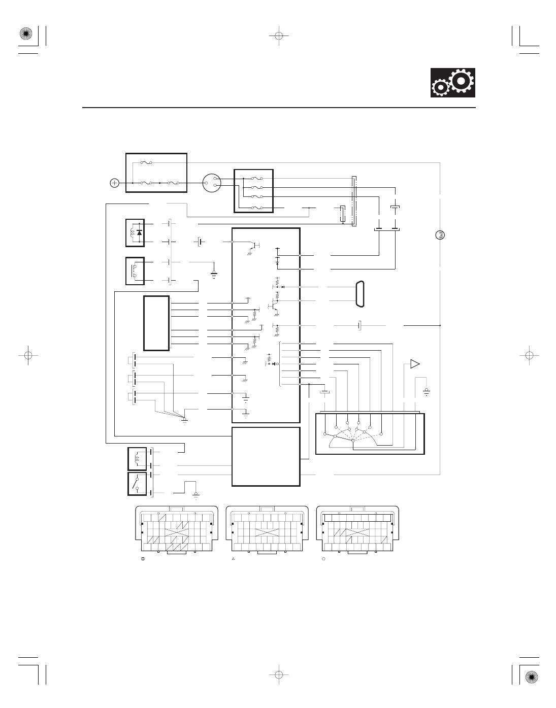
Circuit Diagram
To 5 V
A43
A31
SCS
BRN
LT BLU
K LINE
WHT/BLK
WHT/BLK
WHT/BLK
G102
BLU/WHT
10
ST
N13
P16
P2
P13
P15
YEL/RED
P PIN SW
YEL/BLU
G401
YEL/RED
YEL/RED
YEL/RED
D9
GRN
ORN
BLK
A24
VCC3
APSA
A17
A34
SG3
SG4
A35
A18
APSB
VCC4
A25
RED
YEL
WHT
5
4
6
1
3
2
N36
D1
X38
N44
A5
A6
G1
*1 : ’06 model
*2 : ’07-08 models
SLS
A2
YEL*
YEL/RED*
YEL/BLK
BLK
YEL/BLK
RED
BLK
BLK
BLK
2
1
6
5
IG1
BAT
ACC
IGNITION SWITCH
PG2
PG1
LG1
LG2
B36
C40
B1
B43
BRN/YEL
BRN/YEL
BLK
BLK
G101
G102
*2
*1
UNDER DASH FUSE/RELAY BOX
No.32 (7.5 A)
No.18 (15 A)
No.21 (7.5 A)
No.19 (15 A)
BLK/GRN
BLK/GRN
BLK/YEL
IG1
B37
BLK/YEL
BLK/YEL
VB SOL
B2
To 12 V
C
(44P)
PCM Connector Harness Terminal Locations
A
Terminal side of female terminals
(44P)
(44P)
B
A12
RED/BLK
WHT
ATP FWD
ATP P
ATP R
ATP N
ATP D
ATP 2
ATP 1
C17
C31
C32
C34
C30
C33
YEL/GRN
BLU
BRN
BLU/YEL
7
2
8
3
4
1
9
5
BLK
FWD
2
P
R
N
TRANSMISSION RANGE SWITCH
D
E
1
G101
BLU/BLK
BK SW
WHT/BLK
RED
No.13 (20 A)
A8
BK SW
2
1
3
4
IG KEY SW
KEY SOL
G401
WHT/GRN
RED/WHT
BLK
ATP P
BLU/BLK
UNDER HOOD FUSE/RELAY BOX
No.23 (50 A)
No.22 (120 A)
BATTERY
BRAKE
PEDAL
POSITION
SWITCH
KEY
INTERLOCK
SOLENOID
IGNITION
KEY
SWITCH
POWERTRAIN
CONTROL
MODULE (PCM)
MULTIPLEX
INTEGRATED
CONTROL
UNIT (MICU)
STARTER
CUT
RELAY
IG1 HOT in ON (II)
and START (III)
SHIFT LOCK
SOLENOID
PARK PIN
SWITCH
ACCELERATOR
PEDAL
POSITION
SENSOR
ACC HOT in
ACC (I) and ON (II)
DATA LINK
CONNECTOR
(DLC)
2
1
31
1
2
3
4
5
6
9
8
7
11
10
15
14
13
17 18
16
32
30
42
37
38
40
39
36
20
27
19
25
24
34
23
33
26
28
41
12
44
43
36
41
44
43
42
27 28
30
33 34 35
32
25
20 21 22
16
18
17
13 14 15
12
11
7
8
9
6
3
1
23
23
31
4
5
6
14
22
21
20
24
34
29
28
42
44
38
36
18
17
8
10
2
26
29
37
39
38
1
7
11 12
43
5
4
24
19
40
10
19
33
9
35
25
37
13
2
31