Honda Ridgeline. Manual - part 222


  Index      Honda     Honda Ridgeline - service repair manual 2006-2008 year


Search            


Content   ..  220  221  222  223   ..


Honda Ridgeline. Manual - part 222


01

02

03

SJC8A00E10410759811KBAT00

14-273

Transmission Range Switch Replacement

6 x 1.0 mm
9.8 N·m
(1.0 kgf·m, 7.2 lbf·ft)

A

B

C

D

E

A

B

C

D

F

G

E

H

B

A

C

1. Make sure you have the anti-theft codes for the

audio system and the navigation system (if
equipped).

2. Disconnect the negative cable from the battery,

then disconnect the positive cable.

3. Remove the battery hold-down bracket, and

remove the battery and the battery tray.

4. Remove the intake manifold cover, the intake air

duct, the resonator, and the air cleaner housing.

5. Remove the battery base and the battery base

bracket.

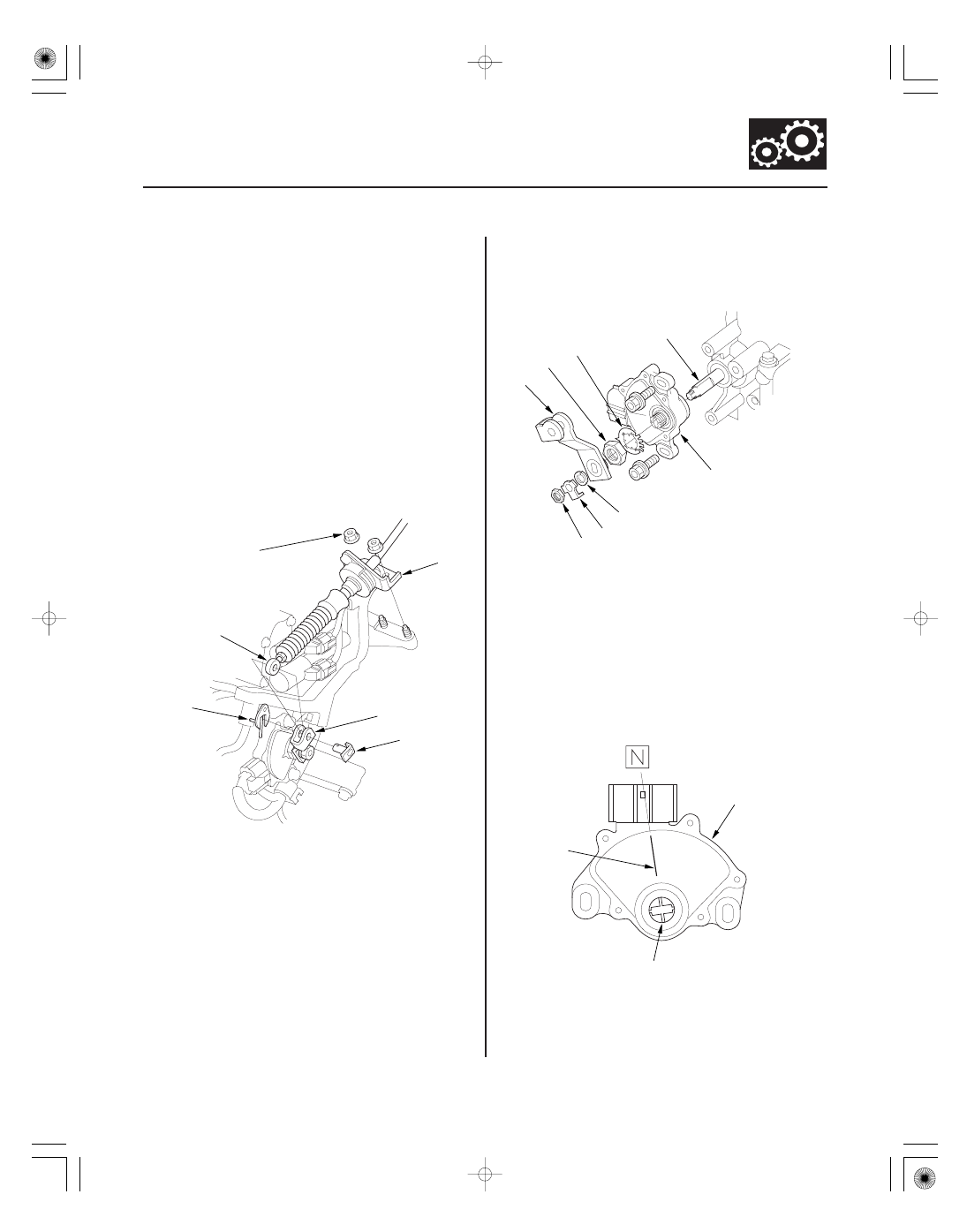
6. Remove the nuts securing the shift cable bracket

(A).

7. Remove the spring clip/washer (B) and the control

pin (C), then separate the shift cable end (D) from
the control lever (E).

8. Disconnect the transmission range switch

connector.

9. Pry the lock tab of the lock washer (A) on the

control lever (B), and remove the nut (C), the lock
washer, the spring washer (D), and the control
lever.

10. Pry the lock tabs of the lock washer (E) on the

transmission range switch (F), hold the selector
control shaft (G) with a 6.0 mm wrench, and loosen
the locknut (H).

11. Remove the locknut and lock washer, then remove

the transmission range switch (two bolts).

12. Set the new transmission range switch (A) to the N

position. The transmission range switch clicks in
the N position, and the control shaft hole (B) aligns
with the N position line (C).

(cont’d)

*01

05

06

07

14-274

A/T Gear Position Indicator

Transmission Range Switch Replacement (cont’d)

B

A

6 x 1.0 mm
12 N·m
(1.2 kgf·m, 8.7 lbf·ft)

E

B

F
12 N·m
(1.2 kgf·m,
8.7 lbf·ft)

D

C

A

13. With a 6.0 mm wrench, turn the control shaft fully

counterclockwise (view from shaft end) to P. Turn
the control shaft back two click-stopped position so
that the shift position is in N.

14. Install the transmission range switch (A) gently

over the selector control shaft (B), and install the
bolts loosely.

15. Install the new lock washer (A) over the selector

control shaft (B) while aligning the projection (C) of
the lock washer with the N positioning line (D) on
the transmission range switch (E), and install the
locknut (F).

16. Push the locknut against the transmission housing

to seat the transmission range switch into the
control shaft, and tighten the locknut to 12 N·m
(1.2 kgf·m, 8.7 lbf·ft) while holding the control shaft
with a 6.0 mm wrench, then bend the lock tabs
against the locknut.

17. Tighten the bolts to 12 N·m (1.2 kgf·m, 8.7 lbf·ft)

securing the transmission range switch.

08

14-275

A

B

C

E

D
12 N·m
(1.2 kgf·m, 8.7 lbf·ft)

18. Install the control lever (A), the spring washer (B),

the lock washer (C), and the locknut (D) on the
selector control shaft (E).

19. Tighten the locknut to the specified torque, then

bend the lock tab of the lock washer against the
locknut.

20. Attach the shift cable end to the control lever, then

insert the control pin into the control lever hole
through the shift cable end, and secure the control
pin with the spring clip/washer.

21. Secure the shift cable bracket.

22. Check the connectors for rust, dirt, or oil, clean or

repair if necessary, then connect the connector
securely.

23. Install the battery base bracket and the battery base.

24. Install the air cleaner housing, the resonator, the

intake air duct, and the intake manifold cover.

25. Install the battery tray, the battery, and the battery

hold-down bracket, then connect the battery cables.

26. Turn the ignition switch to ON (II). Move the shift

lever through all positions, and check the
transmission range switch synchronization with the
A/T gear position indicator.

27. Check that the engine will start in the P and N

positions, and will not start in any other shift lever
position.

28. Check that the back-up lights come on when the

shift lever is in the R position.

29. Raise the vehicle on a lift, allow all four wheels to

rotate freely, then start the engine, and check the
shift lever operation.

30. Enter the anti-theft codes for the audio system and

the navigation system (if equipped). Set the clock
(on vehicles without navigation).

31. Do the power window control unit reset procedure

(see page 22-209).

01

02

03

SJC8A00E10410612241FHAT00

14-276

A/T Gear Position Indicator

D3 Switch Test/Replacement

D3 SWITCH/SHIFT LOCK SOLENOID/
PARK PIN SWITCH CONNECTOR

D3 SW

GND

A

B

C

D

A

A

B

1. Remove the shift lever assembly (see page 14-243).

2. Check for continuity between D3 switch/shift lock

solenoid/park pin switch connector terminals No. 3
and No. 4 while pressing the D3 switch and when
the switch is released.

3. There should be continuity while pressing the D3

switch, and there should be no continuity when the
D3 switch is released.

4. If the D3 switch tests OK, install the shift lever

assembly (see page 14-245).
If the switch is faulty, go to step 5, and replace the
D3 switch.

5. Remove the harness clamps from the shift lever

bracket, and remove the harnesses from the
harness clamps.

6. Pry up the lock covers (A) of the D3 switch/shift lock

solenoid/park pin switch connector (B).

7. Remove the terminal (C) from the connector by

pushing the lock tab up in the connector using a
thin blade screwdriver (D). Remove all six terminals,
and replace the connector.

8. Pry off the shift lever knob ring (A), and remove it.

9. Unlatch the D3 switch harness clamp on the shift

lever bracket, pry out the D3 switch (B), and pull it
from the knob.

Terminal side of male terminals


Content   ..  220  221  222  223   ..