Honda Ridgeline. Manual - part 221
*01
SJC8A00E10410700000EAAT00
−
−
−
−
14-269
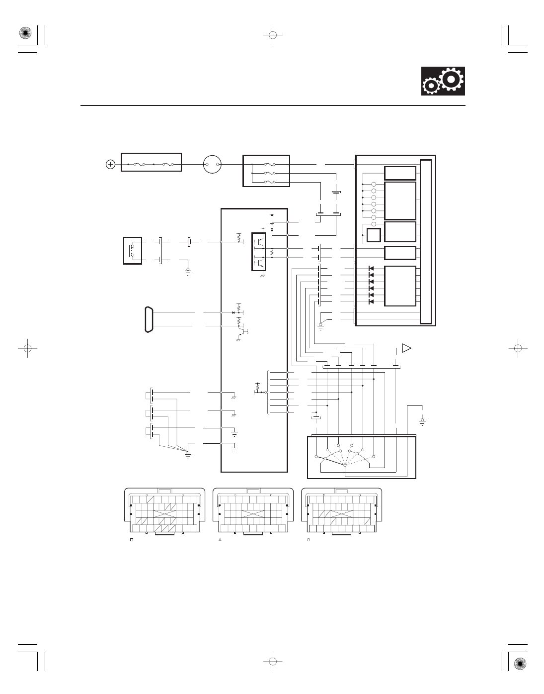
Circuit Diagram
D1
X38
N44
A6
G1
G401
A13
D3 SW
GRN
BLK
GRN
WHT
WHT
3
4
IG1
BAT
BATTERY
No.22 (120 A)
IGNITION SWITCH
No.23 (50 A)
UNDER HOOD FUSE/RELAY BOX
K LINE
LT BLU
A43
A31
BRN
SCS
PG2
PG1
LG1
LG2
B36
C40
B1
B43
BRN/YEL
BRN/YEL
BLK
BLK
G101
G102
UNDER DASH FUSE/RELAY BOX
No.18 (15 A)
No.21 (7.5 A)
No.19 (15 A)
YEL
BLK/GRN
BLK/GRN
BLK/YEL
IG1
B37
BLK/YEL
BLK/YEL
VB SOL
B2
A20
CAN L
CAN H
A36
A1
WHT
WHT
RED
RED
B1
B8
To 5 V
C6
BLU/BLK
C4
WHT
C5
RED/BLK
C7
YEL/GRN
C9
BLU
BRN
C8
G402
BLU/WHT
BRN
BLU
YEL/GRN
RED/BLK
WHT
(44P)
C
B
(44P)
(44P)
Terminal side of female terminals
A
PCM Connector Harness Terminal Locations
G102
GAUGE CONTROL MODULE
To 12 V
CPU
A10
C10
BLU/BLK
WHT
BLU/BLK
BLU/WHT
G401
BLK
BLK
1
9
2
8
3
4
7
1
10
5
A12
RED/BLK
BLU/YEL
BLK
FWD
D
ST
P
R
N
TRANSMISSION RANGE SWITCH
E
2
C17
ATP FWD
ATP 1
ATP P
ATP R
ATP N
ATP D
ATP 2
C34
G101
C31
C32
C33
C30
YEL/GRN
BLU
BRN
2
1
D
N
R
P
STARTER
CUT
RELAY
POWERTRAIN
CONTROL
MODULE (PCM)
F CAN
TRANSCEIVER
WARNING
INDICATOR
DRIVER
A/T
TEMP
TRANSMISSION
RANGE SWITCH
I/F CIRCUIT
SHIFT
POSITION
INDICATOR
DRIVER
DIMMING
CANCEL
CIRCUIT
DATA LINK
CONNECTOR
(DLC)
IG1 HOT in ON (II)
and START (III)
D3
SWITCH
43
44
12
31
2
13
37
25
35
9
33
19
10
41
28
26
33
23
34
24 25
19
40
19
24
4
5
43
12
11
7
1
38
39
37
29
26
2
27
20
10
8
17 18
36
39
40
38
37
42
30
32
16
18
17
13 14 15
10 11
7
8
9
6
5
4
3
2
1
31
36
38
44
42
28 29
34
24
20 21 22
14
6
5
4
31
23
23
1
3
6
9
8
7
11 12
15
14
13
17 18
16
22
21
20
25
32
35
34
33
30
28
27
42
43
44
41
36
D3