Honda Ridgeline. Manual - part 220
01
02
03
SJC8A00E10411412281MBAT00
14-265
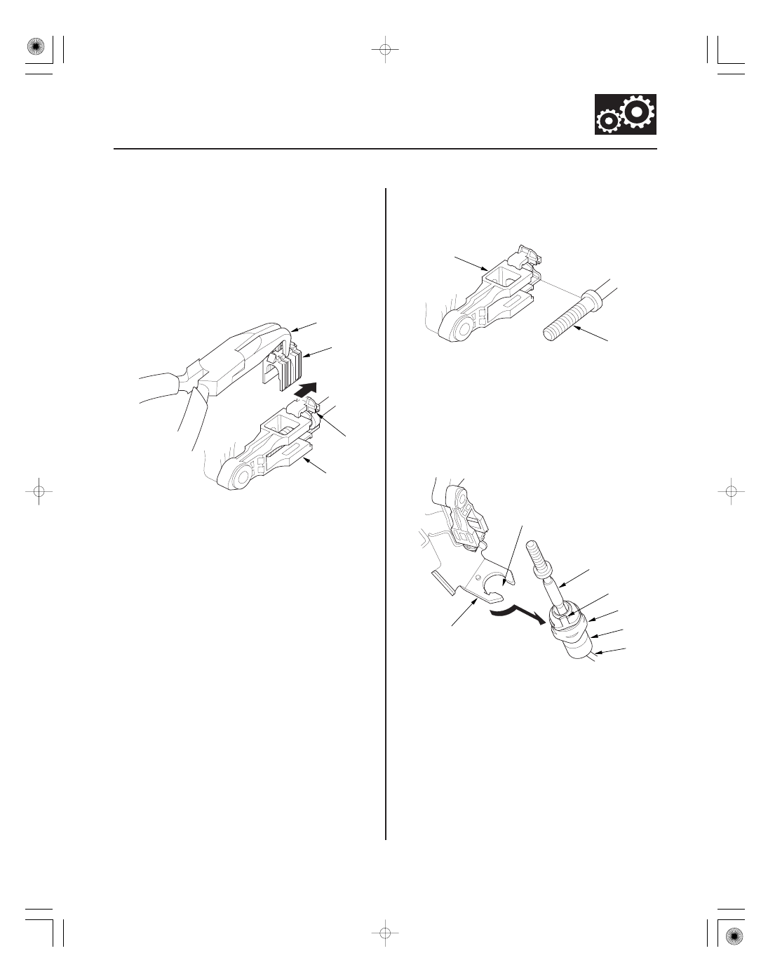
Shift Cable Adjustment
A
B
C
D
A
B
A
B
C
D
F
G
E
1. Remove the driver’s dashboard lower cover
(see page 20-83).
2. Remove the steering column covers (see page
17-24), and lower the steering column.
3. Shift the transmission into R.
4. Slide the lock tab (A) on the shift cable end holder
(B) toward the shift cable socket holder.
5. Grasp the shift cable lock (C) in the middle with
angle-jaw needle-nose pliers (D), and remove it
from the shift cable end and the shift cable end
holder. Do not pry the shift cable lock with a
screwdriver, it may damage the shift cable end
holder.
6. Separate the shift cable end (A) from the shift cable
end holder (B).
7. Rotate the socket holder (A) on the shift cable (B) a
quarter turn; the tab (C) on the socket holder will be
in the opening (D) of the socket holder bracket (E).
Then slide the holder to remove the shift cable
from the socket holder bracket. Do not remove the
shift cable by twisting the shift cable guide (F) and
the damper (G).
(cont’d)