Honda Ridgeline. Manual - part 217
01
02
03
04
SJC8A00E10411412287KBAT77
14-253
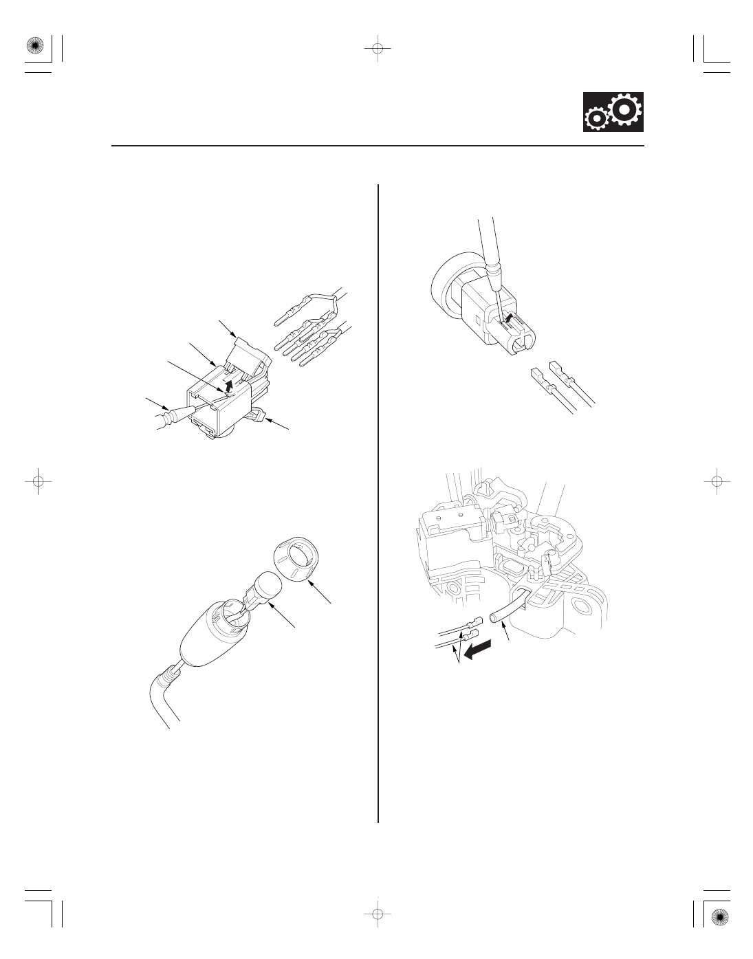
Shift Lever Knob Replacement
A
B
C
D
A
A
B
A
B
1. Remove the shift lever assembly (see page 14-243).
2. Remove the harness clamps from the shift lever
bracket, and remove the harnesses from the
harness clamps.
3. Pry up the lock covers (A) of the D3 switch/shift lock
solenoid/park pin switch connector (B).
4. Remove the terminal from the connector by
pushing the lock tab (C) up in the connector using a
thin blade screwdriver (D). Remove all six terminals,
and replace the connector.
5. Pry off the shift lever knob ring (A), and remove it.
6. Unlatch the D3 switch harness clamp on the shift
lever bracket, pry out the D3 switch (B), and pull it
from the knob.
7. Remove the D3 switch harness terminals by prying
the lock tabs up with a thin blade screwdriver.
8. Pull the D3 switch harness wires (A) from shift lever
bracket side, and remove the harness wires. Leave
the harness tube (B) and remove only the wires.
(cont’d)