Honda Ridgeline. Manual - part 181
*03
−
−
−
−
YES
NO
YES
NO
14-109
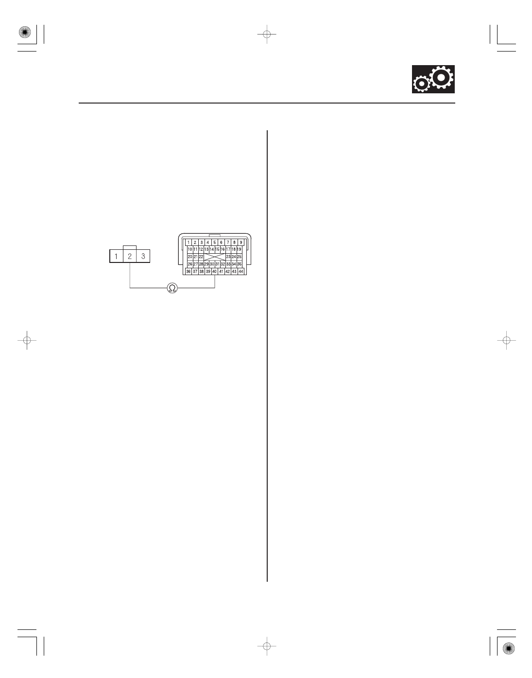
PCM CONNECTOR B (44P)
OUTPUT SHAFT
(COUNTERSHAFT)
SPEED SENSOR
CONNECTOR
NC (BLU)
NC (BLU)
27. Turn the ignition switch to LOCK (0).
28. Jump the SCS line with the HDS.
29. Disconnect PCM connector B (44P).
30. Check for continuity between PCM connector
terminal B40 and output shaft (countershaft) speed
sensor connector terminal No. 2.
Go to step 43.
Repair an open in the wire between PCM
connector terminal B40 and the output shaft
(countershaft) speed sensor, then go to step 36.
31. Connect the output shaft (countershaft) speed
sensor connector.
32. Clear the DTC with the HDS.
33. Start the engine, disable the VSA by pressing the
VSA OFF button, run the vehicle in D, and hold the
vehicle at speeds over 12 mph (20 km/h) for at least
10 seconds when the transmission is not shifting.
Slow down and stop the wheels.
34. Monitor the OBD STATUS for P0721 or P0722 in the
DTCs MENU with the HDS.
Go to step 43.
Go to step 35.
(cont’d)
Wire side of
female terminals
Terminal side of
female terminals
Is ther e continuity?
Does the scr een indicate PASSED?