Honda Ridgeline. Manual - part 178
02
*01
−
−
−
−
YES
NO
YES
NO
14-97
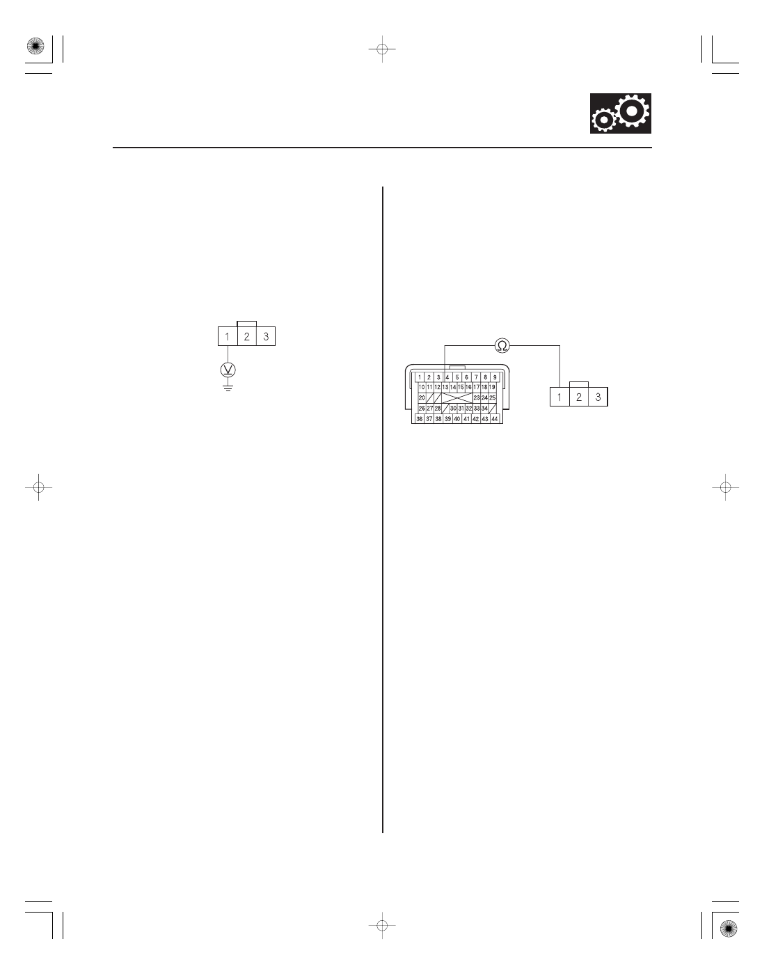
INPUT SHAFT (MAINSHAFT)
SPEED SENSOR CONNECTOR
VCC2 (YEL/BLU)
PCM CONNECTOR C (44P)
INPUT SHAFT
(MAINSHAFT)
SPEED SENSOR
CONNECTOR
VCC2
(YEL/BLU)
VCC2 (YEL/BLU)
11. Connect PCM connectors B (44P) and C (44P).
12. Turn the ignition switch to ON (II).
13. Measure the voltage between input shaft
(mainshaft) speed sensor connector terminal No. 1
and body ground.
Go to step 19.
Go to step 14.
14. Turn the ignition switch to LOCK (0).
15. Jump the SCS line with the HDS.
16. Disconnect PCM connector C (44P).
17. Check for continuity between PCM connector
terminal C13 and input shaft (mainshaft) speed
sensor connector terminal No. 1.
Go to step 18.
Repair an open in the wire between PCM
connector terminal C13 and the input shaft
(mainshaft) speed sensor, then go to step 37.
(cont’d)
Wire side of female terminals
Wire side of
female terminals
Terminal side of
female terminals
Is ther e about 5 V ?
Is ther e continuity?