Honda Ridgeline. Manual - part 177
01
01
SJC8A00K77100090713FAAT00
−
−
−
−
−
−
DTC P0713:
YES
NO
YES
NO
YES
NO
14-93
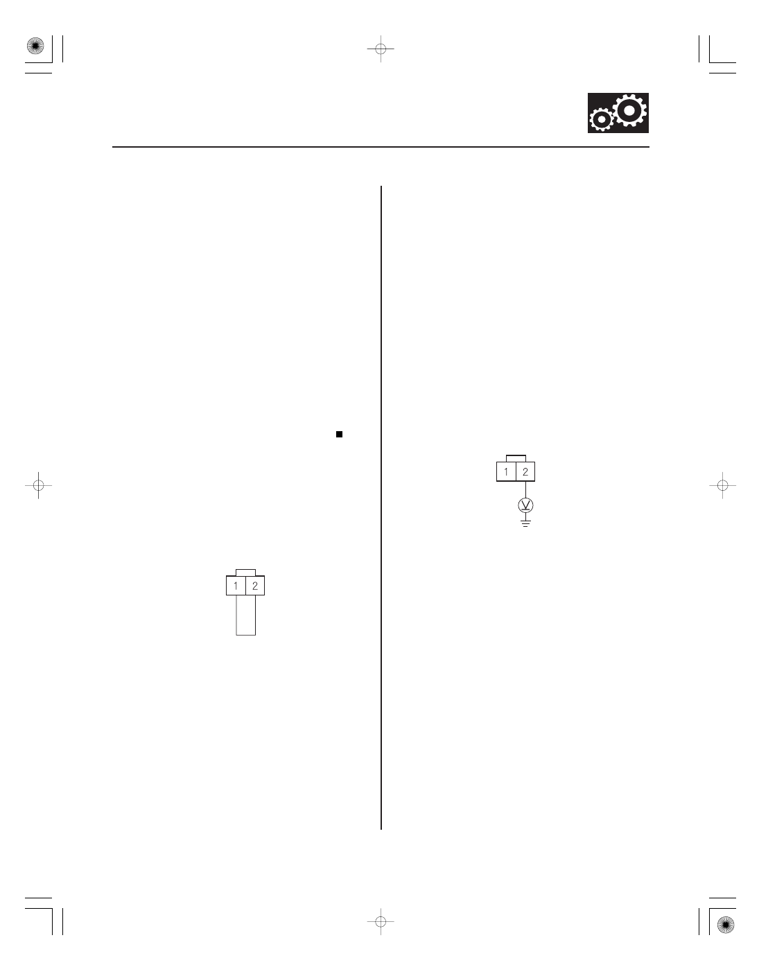
ATF TEMPERATURE
SENSOR CONNECTOR
ATFT (BLU/YEL)
SG2 (GRN/YEL)
JUMPER WIRE
ATF TEMPERATURE
SENSOR CONNECTOR
ATFT (BLU/YEL)
Open in ATF Temperature Sensor
Circuit
NOTE:
• Before you troubleshoot, record all freeze data and
any on-board snapshot, and review General
Troubleshooting Information (see page 14-4).
• This code is caused by an electrical circuit problem
and cannot be caused by a mechanical problem in the
transmission.
1. Check the ATF TEMP SENSOR voltage in the DATA
LIST with the HDS.
Go to step 2.
Intermittent failure, the system is OK at this
time. Check for poor connections or loose terminals
at the ATF temperature sensor and the PCM.
2. Turn the ignition switch to LOCK (0).
3. Disconnect the shift solenoid harness connector.
4. Connect ATF temperature sensor connector
terminals No. 1 and No. 2 with a jumper wire.
5. Turn the ignition switch to ON (II).
6. Check the ATF TEMP SENSOR voltage in the DATA
LIST with the HDS.
Go to step 7.
Go to step 22.
7. Turn the ignition switch to LOCK (0).
8. Remove the jumper wire from the shift solenoid
harness connector.
9. Turn the ignition switch to ON (II).
10. Measure the voltage between ATF temperature
sensor connector terminal No. 2 and body ground.
Go to step 16.
Go to step 11.
11. Turn the ignition switch to LOCK (0).
12. Jump the SCS line with the HDS.
13. Disconnect PCM connector C (44P).
(cont’d)
Wire side of female terminals
Wire side of female terminals
Does the AT F T EMP SENSOR voltage exceed
4.93 V ?
Does the AT F T EMP SENSOR voltage exceed
4.93 V ?
Is ther e about 5 V ?