Honda Ridgeline. Manual - part 172
04
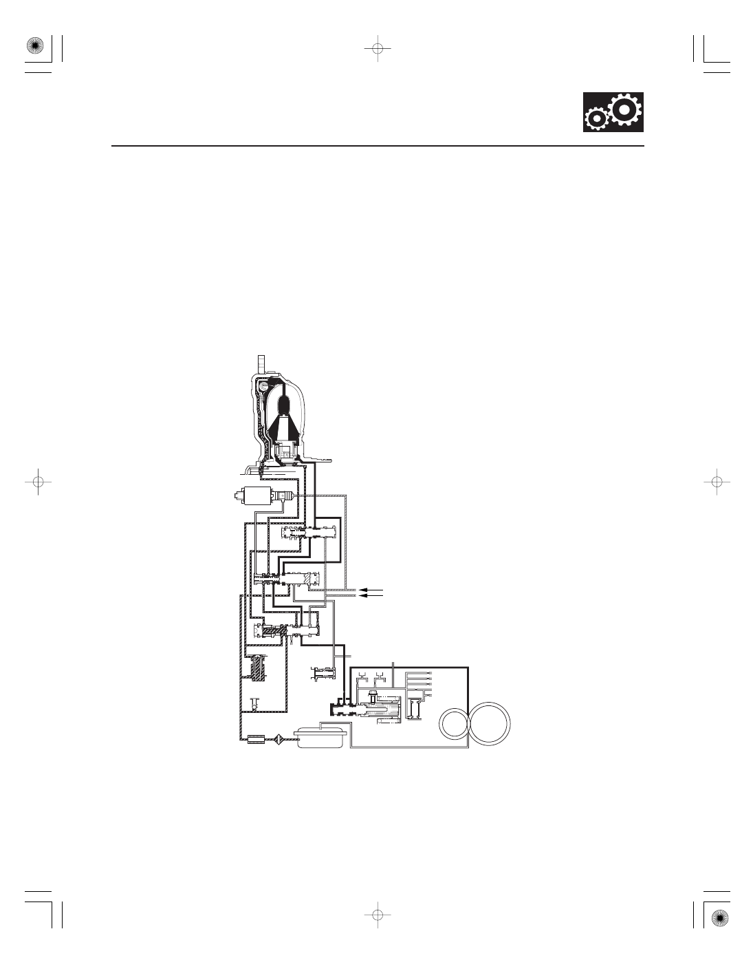
Partial Lock-up
14-73
TORQUE CONVERTER
CLUTCH SOLENOID
VALVE
94
90
91
TORQUE
CONVERTER
6
LA
90
91
X
90’ 91’
58
96
92
93
95
X 6
90’
96
58 97
X
92
LOCK-UP
CONTROL
VALVE
X
X
RELIEF VALVE
90
93
93
X
COOLER CHECK
VALVE
ATF COOLER
99
1
92
1
REGULATOR
VALVE
95’
LUBRICATION
CHECK VALVE
ATF PUMP
X
X
95
MODULATOR PRESSURE (6)
LS C PRESSURE (58)
FILTER
91
91’
94
LA
90
X
95
LOCK-UP
TIMING VALVE
AX
AX
LOCK-UP
SHIFT VALVE
HX
hX
TORQUE
CONVERTER
CHECK VALVE
FINAL GEAR
MAINSHAFT
COUNTERSHAFT
INTERMEDIARY
SHAFT
SECONDARY SHAFT
As the speed of the vehicle reaches the prescribed value, the torque converter clutch solenoid valve is turned ON by
the PCM to release LC pressure (LA) in the left cavity of the lock-up shift valve. Modulator pressure (6) is applied to the
right side of the lock-up shift valve, then the lock-up shift valve is moved in the left side to switch the port leading
torque converter pressure to the right side of the torque converter. Torque converter pressure (91) is applied to the
right side of the torque converter to engage the lock-up clutch. The PCM also controls A/T clutch pressure control
solenoid valve C, and LS C pressure (58) is applied to the lock-up control valve and the lock-up timing valve. When LS
C pressure (58) is lower, torque converter pressure (91) from the lock-up timing valve is lower. The torque converter
clutch is engaged partially. LS C pressure (58) increases, and the lock-up timing valve is moved to the left side to
uncover the port leading torque converter pressure to high. The torque converter clutch is then engaged securely.
Under this condition, the torque converter clutch is engaged by pressure from the right side of the torque converter;
this condition is partial lock-up.
NOTE: When used, ‘‘left’’ or ‘‘right’’ indicates direction on the hydraulic circuit.
(cont’d)