Honda Ridgeline. Manual - part 165
 

  Index      Honda     Honda Ridgeline - service repair manual 2006-2008 year


Search            


Content   ..  163  164  165  166   ..


Honda Ridgeline. Manual - part 165


*07

Lock-up Control

14-45

PCM

Fail-safe Control

Engine RPM Signal

Engine Coolant
Temperature
Sensor Signal

Barometric Pressure
Sensor Signal

Accelerator Pedal
Position Sensor Signal

Input Shaft
(Mainshaft)
Speed Sensor Signal

Output Shaft
(Countershaft)
Speed Sensor Signal

Lock-up Condition
Learning Control

ATF Temperature
Sensor Signal

A/T Clutch Pressure
Control Solenoid
Valve C

Throttle Position
Sensor Signal (DBW)

Engine Coolant
Temperature Control

Current
Feedback

Shifting Position
Control

Gradient Control
by Magnitude

Lock-up Control

Torque Converter
Clutch Solenoid Valve

Transmission Range
Switch Signal

Lock-up ON/OFF Control
Lock-up Condition
Control

Actual
Driving
Shift
Position

Driving Shift
Position
Information

Correction of
ATF Temperature
Sensor Data

Master Target
of Controlling
Current

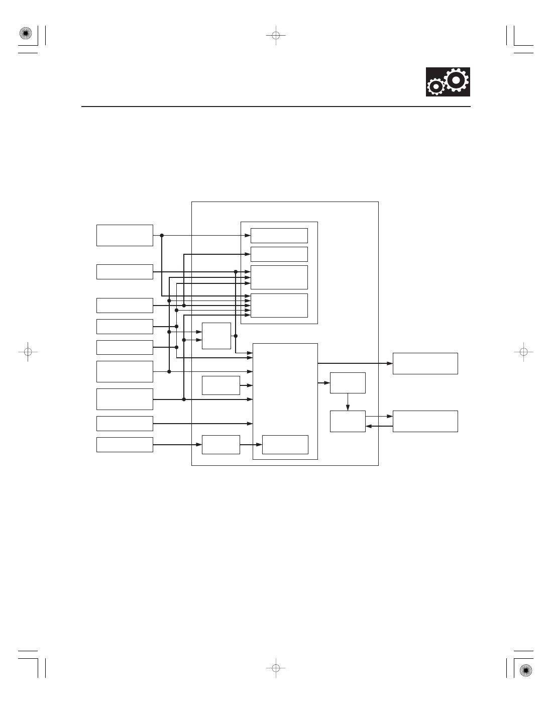
The torque converter clutch solenoid valve controls the hydraulic pressure to switch the lock-up shift valve and lock-up
ON and OFF. The PCM actuates the torque converter clutch solenoid valve and the A/T clutch pressure control
solenoid valve ON, the condition of the lock-up starts. A/T clutch pressure control solenoid valve C regulates and
applies the hydraulic pressure to the lock-up control valve to control the amount of lock-up.
The lock-up mechanism operates in the D position (2nd, 3rd, 4th, and 5th), and in the D position D3 driving mode (2nd
and 3rd).

(cont’d)

*03

Electronic Control System (cont’d)

PCM A/T Control System Electrical Connections

14-46

Automatic Transmission

System Description (cont’d)

43

44

12

31

2

13

37

25

35

9

33

19

10

41

28

26

33

23

34

24 25

19

40

19

24

4

5

43

12

11

7

1

38

39

37

29

26

2

27

20

10

8

17 18

36

39

40

38

37

42

30

32

16

18

17

13 14 15

10 11

7

8

9

6

5

4

3

2

1

31

36

38

44

42

28 29

34

24

20 21 22

14

6

5

4

31

23

23

1

3

6

9

8

7

11 12

15

14

13

17 18

16

22

21

20

25

32

35

34

33

30

28

27

42

43

44

41

36

*1 : ’06 model
*2 : ’07-08 models

(44P)

C

B

(44P)

(44P)

B30

MAP

EGRP

C20

C9

EGR

D3 SWITCH

A13

D3 SW

Shift Position Indicator Driver

A/T TEMP

*2

*1

ACC

VB SOL

B2

A43

K LINE

CPU

C34

ATP 1

C16

C15

B18

C13

VCC1

NC

B40

SG1

B33

1

CAN H

A36

CAN L

A1

Terminal side of female terminals

A

PCM Connector Harness Terminal Locations

B43

C40

B1

B36

1

2

C14

SG2

B39

NM

VCC2

ATFT

C28

C23

SH B

SH A

C25

C18

SH C

B44

LC

LS C

B35

B25

LS B

PG1

C17

ATP FWD

N

BAT

D

PG2

ATP P

A12

DATA LINK CONNECTOR

ATP 2

2

R

Warning Indicator Driver

LG1

ATP R

C30

SCS

IGNITION SWITCH

LG2

GAUGE CONTROL MODULE

OP4SW

OP3SW

ATP D

C31

P

D3

R

P

N

D

C32

ATP N

C33

BK SW

A8

BRAKE LIGHTS

A31

A2

SLS

PCM

B37

IG1

C19

LS A

BATTERY

IG1

BRAKE PEDAL
POSITION SWITCH

SHIFT LOCK
SOLENOID

TRANSMISSION
RANGE SWITCH

A/T CLUTCH PRESSURE
CONTROL SOLENOID VALVE A

A/T CLUTCH PRESSURE
CONTROL SOLENOID VALVE B

A/T CLUTCH PRESSURE
CONTROL SOLENOID VALVE C

SHIFT SOLENOID
VALVE A

SHIFT SOLENOID
VALVE B

SHIFT SOLENOID
VALVE C

TORQUE CONVERTER
CLUTCH SOLENOID VALVE

ATF
TEMPERATURE
SENSOR

OUTPUT SHAFT
(COUNTERSHAFT)
SPEED SENSOR

3RD CLUTCH TRANSMISSION
FLUID PRESSURE SWITCH

4TH CLUTCH TRANSMISSION
FLUID PRESSURE SWITCH

INPUT SHAFT
(MAINSHAFT)
SPEED SENSOR

Dimming
Cancel
Circuit

IG1 HOT in ON (II)
and START (III)

F CAN
Transceiver

Transmission Range
Switch/F Circuit

EGR VALVE
POSITION
SENSOR

MANIFOLD
ABSOLUTE
PRESSURE (MAP)
SENSOR

ACC HOT in
ACC (I) and ON (II)

12

PCM A/T Control System Inputs and Outputs

PCM CONNECTOR A

(44P)

Terminal

number

Wire color

Signal

Description

Measuring conditions/Terminal voltage

14-47

PCM Connector Harness Terminal Locations

A

(44P)

B

(44P)

C

(44P)

A1

RED

CAN L

Sends communication signal

With ignition switch to ON (II): About 2.5 V
(pulses)

A2

YEL/BLK

SLS

Drives shift lock solenoid

With ignition switch to ON (II), in P, brake
pedal pressed, and accelerator released:
About 0 V

A8

WHT/BLK

BK SW

Brake pedal position switch
signal input

Brake pedal pressed: Battery voltage
Brake pedal released: About 0 V

A12

BLU/BLK

ATP P

Transmission range switch P
position signal input

In P: About 0 V
In other than P: Battery voltage

A13

GRN

D3 SW

D3 switch signal input

With D3 switch released: Battery voltage
With D3 switch pressed: About 0 V

A17

ORN

APSA

Detects accelerator pedal
position sensor A signal

With ignition switch to ON (II) and
accelerator pedal pressed: About 4.65 V
With ignition switch to ON (II) and
accelerator pedal released: About 0.5 V

A18

YEL

APSB

Detects accelerator pedal
position sensor B signal

With ignition switch to ON (II) and
accelerator pedal pressed: About 2.325 V
With ignition switch to ON (II) and
accelerator pedal released: About 0.25 V

A24

GRN

VCC3

Power supply for sensors

With ignition switch to ON (II): About 5.0 V
With ignition switch to LOCK (0): About 0 V

A25

WHT

VCC4

Power supply for sensors

With ignition switch to ON (II): About 5.0 V
With ignition switch to LOCK (0): About 0 V

A31

BRN

SCS

Detects service check signal

With the SCS shorted with the HDS: About
0 V
With the SCS open: About 5.0 V

A34

BLK

SG3

Sensor ground

Less than 1.0 V at all times

A35

RED

SG4

Sensor ground

Less than 1.0 V at all times

A36

WHT

CAN H

Communication signal
outputs

With ignition switch to ON (II): About 2.5 V
(pulses)

A43

LT BLU

K-LINE

Communication line PCM-to-
DLC

With ignition switch to ON (II) and HDS
disconnected: About 10.0 V

(cont’d)

Terminal side of female terminals

13

Electronic Control System (cont’d)

PCM A/T Control System Inputs and Outputs (cont’d)

PCM CONNECTOR B

(44P)

Terminal

number

Wire color

Signal

Description

Measuring conditions/Terminal voltage

14-48

Automatic Transmission

System Description (cont’d)

PCM Connector Harness Terminal Locations

A

(44P)

B

(44P)

C

(44P)

B1

BLK

PG2

Ground

Less than 1.0 V at all times

B2

BLK/YEL

VB SOL

Power supply circuit for
solenoid valves

With ignition switch to ON (II): Battery
voltage
With ignition switch to LOCK (0): About 0 V

B18

YEL/RED

VCC1

Power supply circuit

With ignition switch to ON (II): About 5.0 V

B25

BRN/WHT

LS B

A/T clutch pressure control
solenoid valve B control

With ignition switch to ON (II): Duty
controlled

B30

GRN/RED

MAP

Detects manifold absolute
pressure sensor signal

With ignition switch to ON (II): About 3.0 V
At idle: About 1.0 V depending on engine
speed

B33

GRN/WHT

SG1

Sensor ground

Less than 1.0 V at all times

B35

GRN/RED

LS C

A/T clutch pressure control
solenoid valve C control

With ignition switch to ON (II): Duty
controlled

B36

BLK

PG1

Ground

Less than 1.0 V at all times

B37

BLK/YEL

IG1

Power supply circuit

With ignition switch to ON (II): Battery
voltage
With ignition switch to LOCK (0): About 0 V

B39

RED

NM

Input shaft (mainshaft) speed
sensor signal input

With ignition switch to ON (II): About 0 V or
about 5.0 V
With engine at idle in N: About 2.5 V
(pulses)

B40

BLU

NC

Output shaft (countershaft)
speed sensor signal input

With ignition switch to ON (II): About 0 V or
about 5.0 V
With vehicle moving: About 2.5 V (pulses)

B43

BRN/YEL

LG2

Ground

Less than 1.0 V at all times

B44

YEL

LC

Torque converter clutch
solenoid valve control

During lock-up condition: Battery voltage
During no lock-up condition: About 0 V

Terminal side of female terminals


Content   ..  163  164  165  166   ..