Honda Ridgeline. Manual - part 152
−
−
−
−
−
−
02
03
−
−
−
−
−
−
−
−
YES
NO
YES
NO
YES
NO
YES
NO
11-372
EVAP System
DTC Troubleshooting (cont’d)
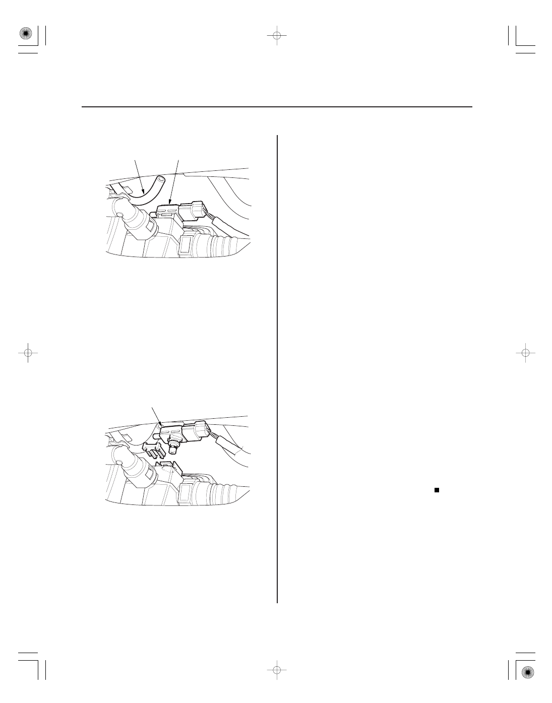
A
B
A
17. Disconnect the air tube (A) from the FTP sensor (B).
18. Check the FTP SENSOR in the DATA LIST with the
HDS.
Check for a blockage in the FTP sensor air
tube or vent, then go to step 23.
Go to step 19.
19. Turn the ignition switch OFF.
20. Remove the FTP sensor (A) from the EVAP canister
with its connector connected (see page 11-374).
21. Turn the ignition switch ON (II).
22. Check the FTP SENSOR in the DATA LIST with the
HDS.
Check for debris or clogging at the EVAP
canister and the FTP sensor port, then go to
step 23.
Replace the FTP sensor (see page 11-374),
then go to step 23.
23. Turn the ignition switch ON (II).
24. Reset the PCM with the HDS.
25. Do the PCM idle learn procedure (see page 11-273).
26. Start the engine. Hold the engine speed at
3,000 rpm without load (in Park or neutral) until the
radiator fan comes on, then let it idle.
27. Check for Temporary DTCs or DTCs with the HDS.
Check for poor connections or loose
terminals at the FTP sensor, the EVAP canister vent
shut valve, and the PCM, then go to step 1.
Go to step 28.
28. Monitor the OBD STATUS for DTC P1454 and/or
P2422 in the DTCs MENU with the HDS.
Troubleshooting is complete. If any other
Temporary DTCs or DTCs were indicated in step 27,
go to the indicated DTC’s troubleshooting.
If the screen indicates FAILED, check for poor
connections or loose terminals at the FTP sensor,
the EVAP canister vent shut valve, and the PCM,
then go to step 1. If the screen indicates NOT
COMPLETED, keep idling until a result comes on.
Is it between
0.67 and 0.67 kPa (
0.2 and
0.2 in.Hg,
5 and 5 mmHg), or 2.4 and 2.6 V ?
Is it between
0.67 kPa and 0.67 kPa (
0.2 and
0.2 in.Hg,
5 and 5 mmHg), or 2.4 and 2.6 V ?
Is DT C P1454 and/ or P2422 indicated?
Does the scr een indicate PASSED?