Honda Ridgeline. Manual - part 95
01
02
SJC8A00K771000916BCFAAT00
−
−
−
−
−
−
−
−
DTC P16BC:
YES
NO
YES
NO
YES
NO
YES
NO
11-144
PGM-FI System
DTC Troubleshooting (cont’d)
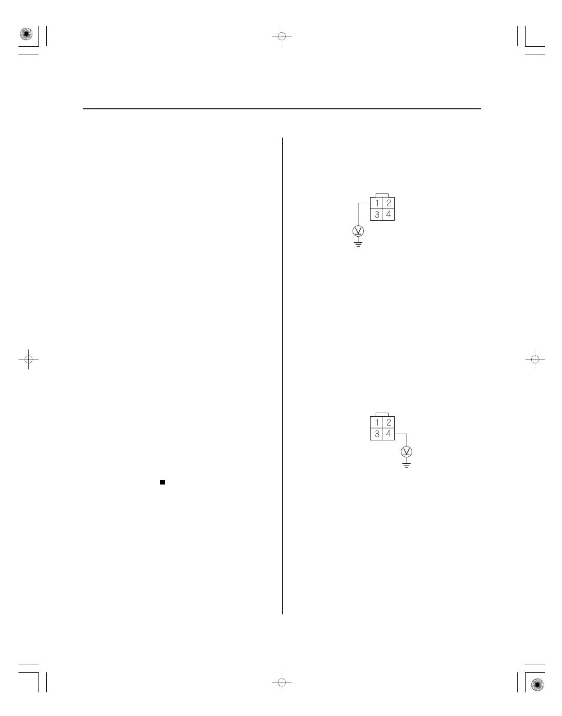
ALTERNATOR 4P CONNECTOR
IG1
(BLK/YEL)
ALTERNATOR 4P CONNECTOR
ALTF
(WHT/RED)
Alternator FR Terminal Circuit/
IGP Circuit Low Voltage
NOTE: Before you troubleshoot, record all freeze data
and any on-board snapshot, and review the general
troubleshooting information (see page 11-3).
1. Check for poor connections at the alternator 4P
connector.
Go to step 2.
Repair the connections, then go to step 18.
2. Turn the ignition switch ON (II).
3. Clear the DTC with the HDS.
4. Start the engine.
5. Check under these conditions:
• A/C on
• Temperature control at maximum cool
• Blower fan at maximum speed
• Headlights on high beam
6. Hold the engine speed at 2,000 rpm (in Park or
neutral) 1 minute.
7. Check for Temporary DTCs or DTCs with the HDS.
Go to step 8.
Intermittent failure, the system is OK at this
time. Check for poor connections or loose terminals
at the alternator.
8. Turn the ignition switch OFF.
9. Disconnect the alternator 4P connector.
10. Turn the ignition switch ON (II).
11. Measure voltage between alternator 4P connector
terminal No. 1 and body ground.
Go to step 12.
Repair open in the wire between the
alternator (IG1 line) and the No. 18 IG ACG (15 A)
fuse in under-dash fuse/relay box, then go to step
18.
12. Measure voltage between alternator 4P connector
terminal No. 4 and body ground.
Replace the alternator (see page 4-34), then
go to step 18.
Go to step 13.
Wire side of female terminals
Wire side of female terminals
Ar e the connections OK ?
Is DT C P16BC indicated?
Is ther e batter y voltage?
Is ther e about 5 V ?