Honda Ridgeline. Manual - part 84
*01
−
−
−
−
−
−
YES
NO
YES
NO
YES
NO
11-100
PGM-FI System
DTC Troubleshooting (cont’d)
07406-0070301
07ZAJ-S5A0200
07406-0020201 or
07MAJ-PY4011A and
07MAJ-PY40120
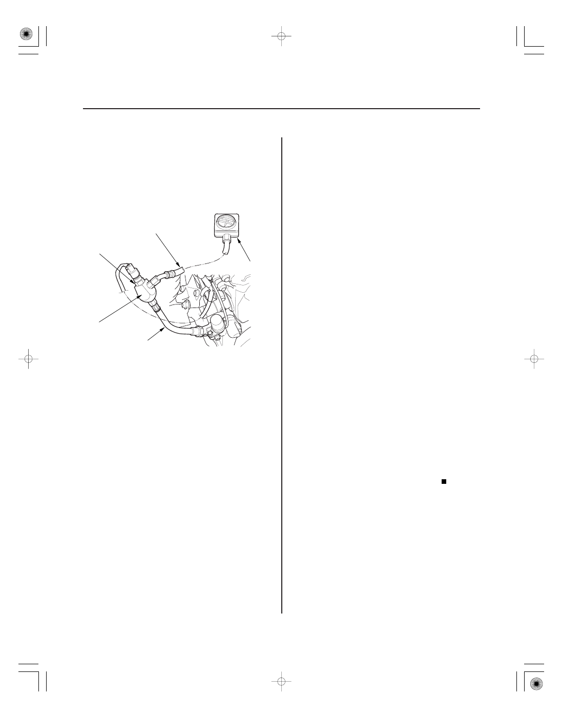
A
22 N·m
(2.2 kgf·m,
16 lbf·ft)
B
07NAJ-P07010A
16. Remove the rocker arm oil pressure switch (VTEC
oil pressure switch) (A), and install the special tools
as shown, then install the rocker arm oil pressure
switch (VTEC oil pressure switch) in the pressure
gauge adapter (B).
NOTE: Install the parts in the reverse order of
removal with a new O-ring.
17. Reconnect the rocker arm oil pressure switch
(VTEC oil pressure switch) 2P connector.
18. Start the engine. Hold the engine speed at
3,000 rpm without load (in Park or neutral) until the
radiator fan comes on.
19. Check the oil pressure at engine speeds of 1,000
and 2,000 rpm. Keep the measuring time as short
as possible (less than 1 minute) because the engine
is running without load.
Check for air in the fuel line, then go to step
20.
Inspect the VTEC system (see page 6-7), then
go to step 20.
20. Turn the ignition switch ON (II).
21. Reset the PCM with the HDS.
22. Clear the CKP pattern with the HDS.
23. Do the PCM idle learn procedure (see page 11-273).
24. Do the CKP pattern learn procedure (see page 11-4).
25. Test-drive the vehicle for several minutes in the
range of these recorded freeze data parameters:
• ENGINE SPEED
• VSS
• REL TP SENSOR
• CLV (calculated load value)
• ECT SENSOR 1
• APP SENSOR
26. Check for Temporary DTCs or DTCs with the HDS.
Check for poor connections or loose
terminals at the ignition coil, the injector, and the
PCM, then go to step 1.
Go to step 27.
27. Monitor the OBD STATUS for DTC P0301, P0302,
P0303, P0304, P0305, or P0306 in the DTCs MENU
with the HDS.
Troubleshooting is complete. If any other
Temporary DTCs or DTCs were indicated in step 26,
go to the indicated DTC’s troubleshooting.
If the screen indicates FAILED, check for poor
connection or loose terminals at the ignitions coil,
the injector, and the PCM, then go to step 1. If the
screen indicates EXECUTING, keep driving until a
result comes on. If the screen indicates OUT OF
CONDITION, go to step 25.
Is the oil pr essur e below 49 kPa ( 0.5 kgf / cm ,
7 psi)?
Is DT C P0300 and any combination of DT C P0301,
P0302, P0303, P0304, P0305, or P0306
indicated?
Does the scr een indicate PASSED?
2