Honda Ridgeline. Manual - part 82
−
01
02
SJC8A00K77100090141FAAT30
−
−
−
−
−
−
−
−
DTC P0141:
DTC P0161:
YES
NO
YES
NO
YES
NO
YES
NO
11-92
PGM-FI System
DTC Troubleshooting (cont’d)
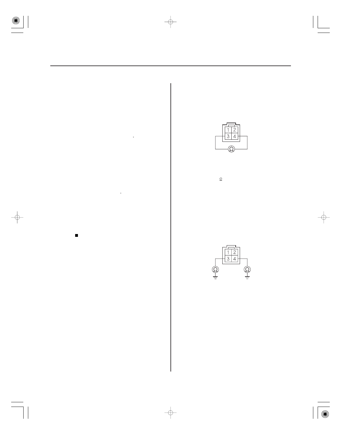
SECONDARY HO2S (SENSOR 2) 4P CONNECTOR
SECONDARY HO2S (SENSOR 2) 4P CONNECTOR
Rear Secondary HO2S (Bank 1,
Sensor 2) Heater Circuit Malfunction
Front Secondary HO2S (Bank 2,
Sensor 2) Heater Circuit Malfunction
NOTE:
• Before you troubleshoot, record all freeze data and
any on-board snapshot, and review the general
troubleshooting information (see page 11-3).
• Information marked with an asterisk ( ) applies to the
front bank (Bank 2).
1. Turn the ignition switch ON (II).
2. Clear the DTC with the HDS.
3. Start the engine.
4. Check for Temporary DTCs or DTCs with the HDS.
Go to step 5.
Intermittent failure, the system is OK at this
time. Check for poor connections or loose terminals
at the secondary HO2S (Sensor 2), the A/F sensor
relay (LAF), the under-dash fuse/relay box, and the
PCM.
5. Turn the ignition switch OFF.
6. Check these fuses:
• No. 17 OP1 (40 A) fuse in the under-hood fuse/
relay box
• No. 4 LAF (A/F SENSOR) (15 A) fuse in the under-
dash fuse/relay box
• No. 23 IGP (7.5 A) fuse in the under-dash fuse/
relay box
Repair short in the wire between the A/F
sensors, A/F sensor relay (LAF) and the fuse, then
go to step 23.
Go to step 7.
7. Disconnect the secondary HO2S (Sensor 2) 4P
connector.
8. At the secondary HO2S (Sensor 2) side, measure
resistance between secondary HO2S (Sensor 2) 4P
connector terminals No. 3 and No. 4.
Go to step 9.
Go to step 22.
9. Check for continuity between body ground and
secondary HO2S (Sensor 2) 4P connector terminals
No. 3 and No. 4 individually.
Go to step 22.
Go to step 10.
Terminal side of male terminals
Terminal side of male terminals
Is DT C P0141 and/ or P0161 indicated?
Ar e any of the f uses blown?
Is ther e 5.4
6.6
at r oom temper atur e?
Is ther e continuity?