Honda Ridgeline. Manual - part 76
03
04
−
−
−
−
YES
NO
YES
NO
11-68
PGM-FI System
DTC Troubleshooting (cont’d)
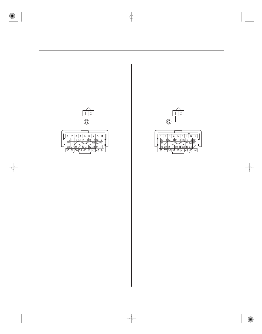
PCM CONNECTOR C (44P)
IAT SENSOR 2P CONNECTOR
SG2 (GRN/YEL)
SG2 (GRN/YEL)
PCM CONNECTOR C (44P)
IAT SENSOR 2P CONNECTOR
IAT (RED/YEL)
IAT (RED/YEL)
12. Turn the ignition switch OFF.
13. Jump the SCS line with the HDS.
14. Disconnect PCM connector C (44P).
15. Check for continuity between PCM connector
terminal C14 and IAT sensor 2P connector terminal
No. 2.
Go to step 27.
Repair open in the wire between the PCM
(C14) and the IAT sensor, then go to step 22.
16. Turn the ignition switch OFF.
17. Jump the SCS line with the HDS.
18. Disconnect PCM connector C (44P).
19. Check for continuity between PCM connector
terminal C26 and IAT sensor 2P connector terminal
No. 1.
Go to step 27.
Repair open in the wire between the PCM
(C26) and the IAT sensor, then go to step 22.
Wire side of
female terminals
Terminal side of female terminals
Wire side of
female terminals
Terminal side of female terminals
Is ther e continuity?
Is ther e continuity?