Honda Ridgeline. Manual - part 74
03
−
−
−
−
−
−
YES
NO
YES
NO
YES
NO
11-60
PGM-FI System
DTC Troubleshooting (cont’d)
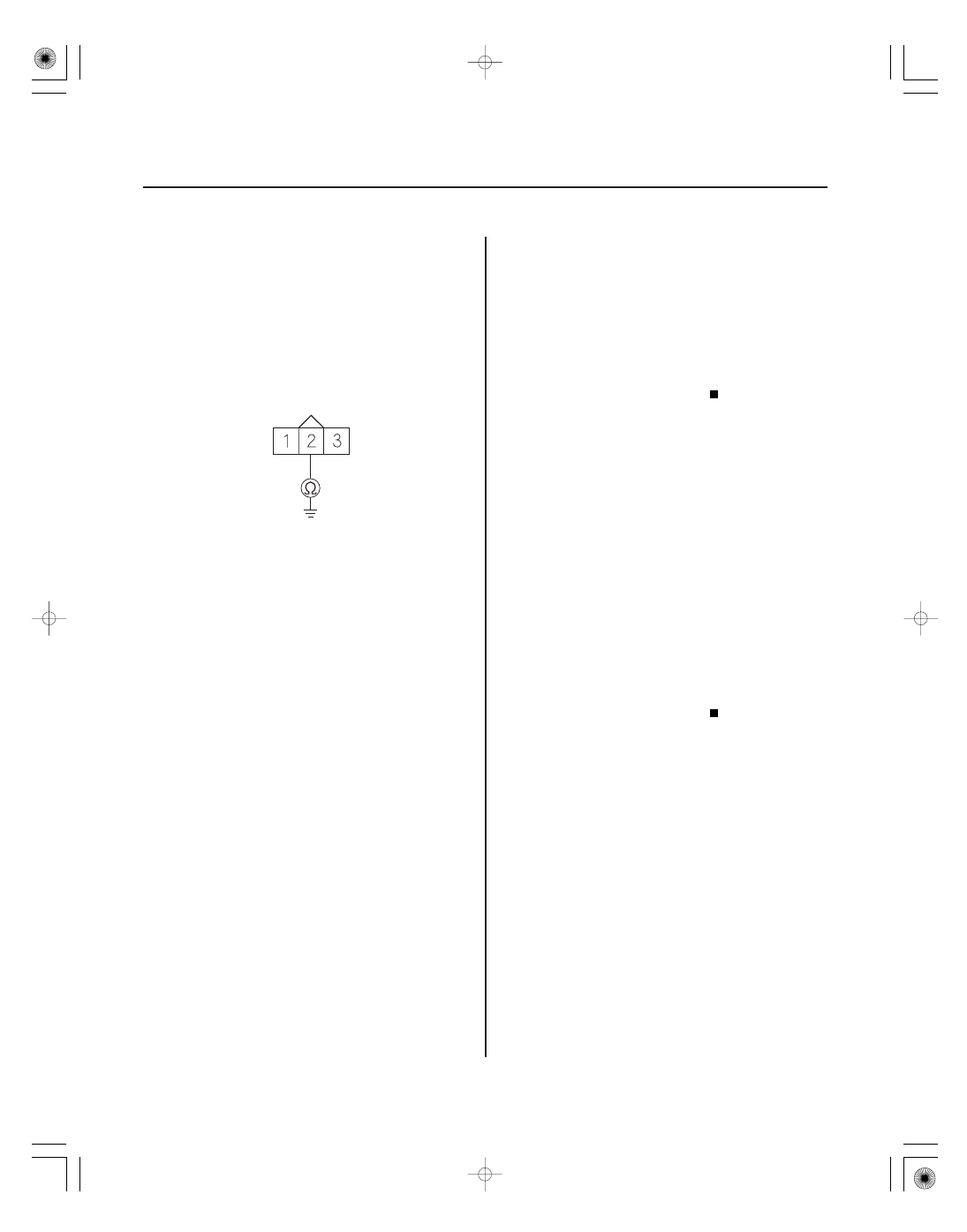
MAP
(GRN/RED)
MAP SENSOR 3P CONNECTOR
12. Turn the ignition switch OFF.
13. Jump the SCS line with the HDS.
14. Disconnect PCM connector B (44P).
15. Check for continuity between MAP sensor 3P
connector terminal No. 2 and body ground.
Repair short in the wire between the PCM
(B30) and the MAP sensor, then go to step 18.
Go to step 23.
16. Turn the ignition switch OFF.
17. Replace the MAP sensor (see page 11-204).
18. Reconnect all connectors.
19. Turn the ignition switch ON (II).
20. Reset the PCM with the HDS.
21. Do the PCM idle learn procedure (see page 11-273).
22. Check for Temporary DTCs or DTCs with the HDS.
Check for poor connections or loose
terminals at the MAP sensor and the PCM, then go
to step 1.
Troubleshooting is complete. If any other
Temporary DTCs or DTCs are indicated, go to the
indicated DTC’s troubleshooting.
23. Reconnect all connectors.
24. Update the PCM if it does not have the latest
software (see page 11-7), or substitute a known-
good PCM (see page 11-8).
25. Check for Temporary DTCs or DTCs with the HDS.
Check for poor connections or loose
terminals at the MAP sensor and the PCM. If the
PCM was updated, substitute a known-good PCM
(see page 11-8), then recheck. If the PCM was
substituted, go to step 1.
If the PCM was updated, troubleshooting is
complete. If the PCM was substituted, replace the
original PCM (see page 11-205). If any other
Temporary DTCs or DTCs are indicated, go to the
indicated DTC’s troubleshooting.
Wire side of female terminals
Is ther e continuity?
Is DT C P0107 indicated?
Is DT C P0107 indicated?