Honda Ridgeline. Manual - part 66
−
+
−
+
−
12
△
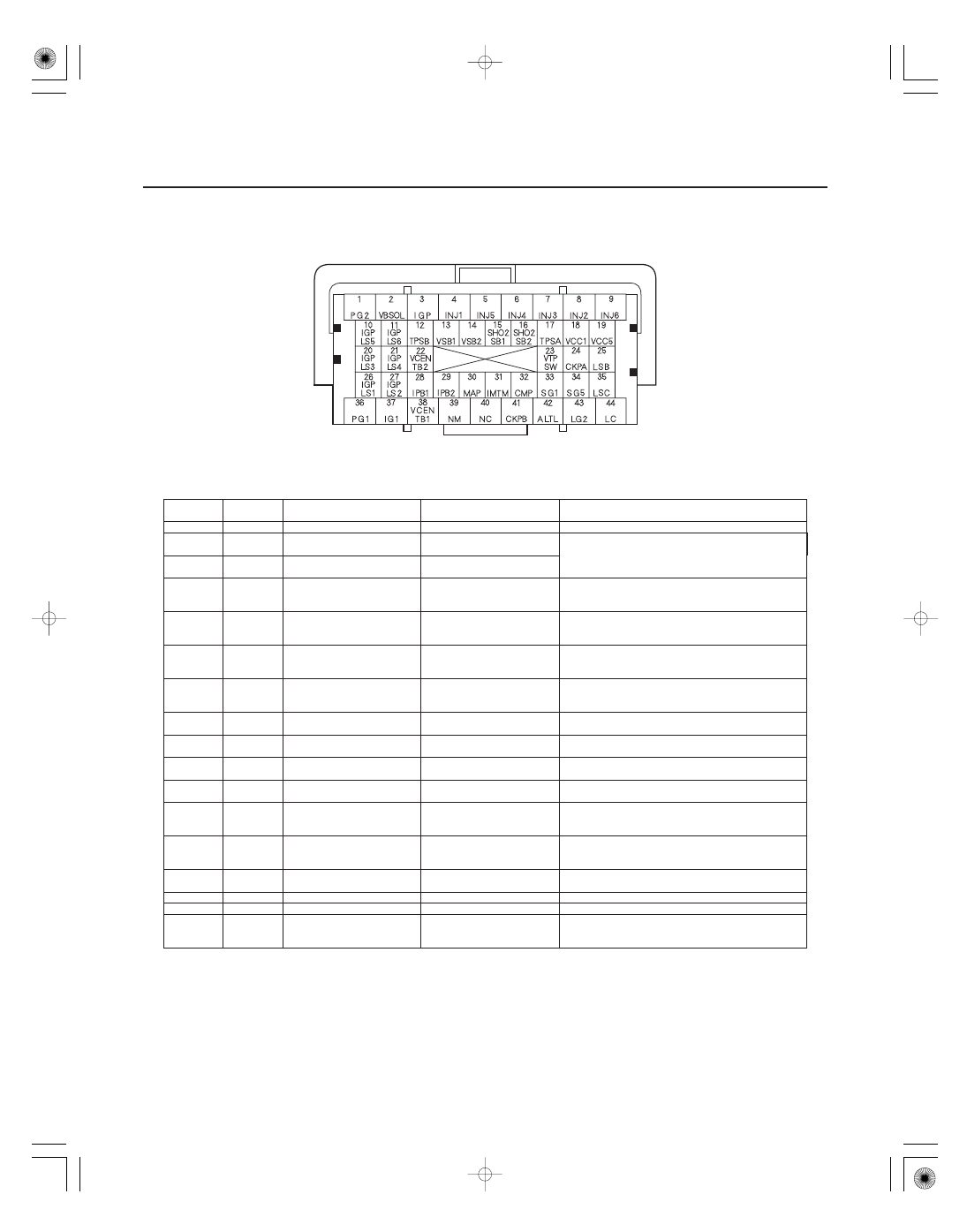
PCM Inputs and Outputs at Connector B (
) (44P)
Terminal
number
Wire color
Terminal name
Description
Signal
11-28
Fuel and Emissions Systems
System Description (cont’d)
NOTE: Standard battery voltage is about 12 V.
19
BLU
VCC5 (SENSOR VOLTAGE)
Provides sensor voltage
With ignition switch ON (II): about 5.0 V
20
WHT/BLU
IGPLS3 (No. 3 IGNITION
COIL PULSE)
Drives No. 3 ignition coil
With ignition switch ON (II): about 0 V
With engine running: pulses
21
BRN
IGPLS4 (No. 4 IGNITION
COIL PULSE)
Drives No. 4 ignition coil
22
RED/WHT
VCENTB2 (VIRTUAL
GROUND BANK 2)
Reference voltage supply
for front A/F sensor (Bank 2,
sensor 1)
With fully warmed up engine at idle:
about 3.4
4.8 V
23
BLU/WHT
VTPSW (ROCKER ARM OIL
PRESSURE SWITCH) (VTEC
PRESSURE SWITCH)
Detects rocker arm oil
pressure switch (VTEC oil
pressure switch) signal
With engine at low speed: about 0 V
With engine at high speed: battery voltage
24
BLU
CKPA (CRANKSHAFT
POSITION (CKP)
SENSOR A)
Detects CKP sensor A signal
With engine running: pulses
25
BRN/WHT
LSB (A/T CLUTCH
PRESSURE CONTROL
SOLENOID VALVE B)
Drives A/T clutch pressure
control solenoid valve B
With ignition switch ON (II): duty controlled
26
YEL/GRN
IGPLS1 (No. 1 IGNITION
COIL PULSE)
Drives No. 1 ignition coil
With ignition switch ON (II): about 0 V
With engine running: pulses
27
BLU/RED
IGPLS2 (No. 2 IGNITION
COIL PULSE)
Drives No. 2 ignition coil
With ignition switch ON (II): about 0 V
With engine running: pulses
28
GRN
IPB1 (IP CELL
BANK 1)
Detects rear A/F sensor
(Bank 1, sensor 1) pump cell
With engine running: about 2.0
5.6 V
29
GRN/RED
IPB2 (IP CELL
BANK 2)
Detects front A/F sensor
(Bank 2, sensor 1) pump cell
With engine running: about 2.0
5.6 V
30
GRN/RED
MAP (MANIFOLD
ABSOLUTE PRESSURE
(MAP) SENSOR)
Detects MAP sensor signal
With ignition switch ON (II): about 3.0 V
At idle: about 1.0 V (depending on engine speed)
31
WHT/BLK
IMTM (INTAKE MANIFOLD
TUNING (IMT) VALVE
MONITOR)
Detects IMT valve position
With ignition switch ON (II): about 5.0 V
With engine speed above 4,000 rpm: about 0 V
32
YEL
CMP (CAMSHAFT
POSITION (CMP) SENSOR)
Detects CMP sensor signal
With engine running: pulses
33
GRN/WHT
SG1 (SENSOR GROUND)
Sensor ground
Less than 1.0 V at all times
34
GRN
SG5 (SENSOR GROUND)
Sensor ground
Less than 1.0 V at all times
35
GRN/RED
LSC (A/T CLUTCH
PRESSURE CONTROL
SOLENOID VALVE C)
Drives A/T clutch pressure
control solenoid valve C
With ignition switch ON (II): duty controlled
Terminal side of female terminals