Honda Ridgeline. Manual - part 47
−
−
01
02
SJC8A00A18360245611KBAT00
−
−
−
−
−
−
−
−
Piston Ring End-Gap
Top Ring:
Standard (New): 0.20
0.35 mm
(0.008
0.014 in.)
Service Limit:
0.60 mm (0.024 in.)
Second Ring:
Standard (New): 0.40
0.55 mm
(0.016
0.022 in.)
Service Limit:
0.70 mm (0.028 in.)
Oil Ring:
Standard (New): 0.20
0.70 mm
(0.008
0.028 in.)
Service Limit:
0.80 mm (0.031 in.)
7-21
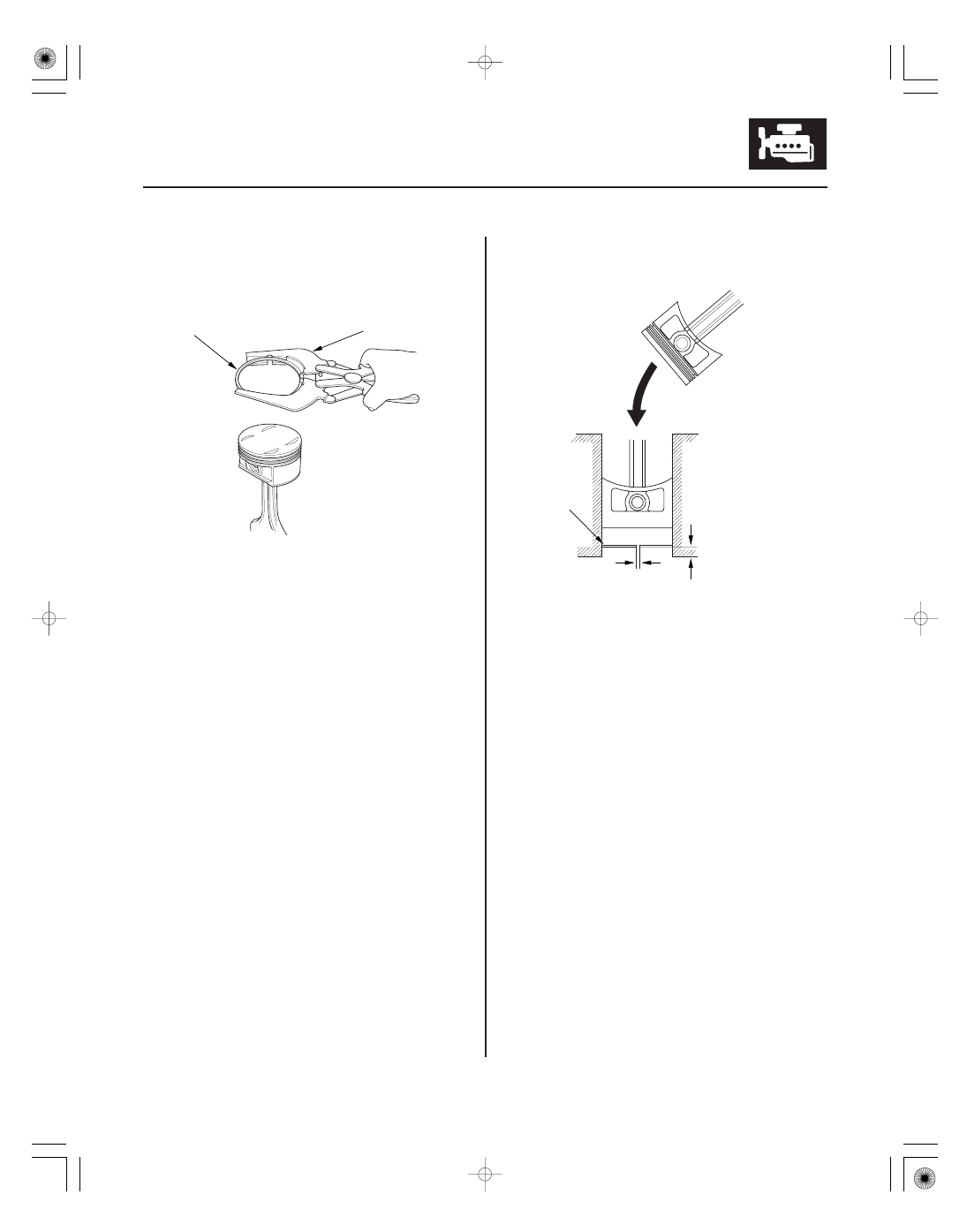
Piston Ring Replacement
A
B
15
20 mm
(0.6
0.8 in.)
B
A
1. Remove the piston from the engine block (see page
7-12).
2. Using a ring expander (A), remove the old piston
rings (B).
3. Clean all the ring grooves thoroughly with a
squared-off broken ring, or a ring groove cleaner
with a blade to fit the piston grooves. File down the
blade, if necessary. The top ring and second ring
grooves are 1.2 mm (0.05 in.) wide, and the oil ring
groove is 2.8 mm (0.11 in.) wide. Do not use a wire
brush to clean the ring grooves, or cut the ring
grooves deeper with the cleaning tool.
NOTE: If the piston is to be separated from the
connecting rod, do not install new rings yet.
4. Using a piston, push a new ring (A) into the
cylinder bore 15
20 mm (0.6
0.8 in.) from the
bottom.
5. Measure the piston ring end-gap (B) with a feeler
gauge:
• If the gap is too small, check to see if you have
the proper rings for your engine.
• If the gap is too large, recheck the cylinder bore
diameter against the wear limits (see step 4 on
page 7-16). If the bore is over the service limit,
the engine block must be rebored.
(cont’d)