Honda Ridgeline. Manual - part 26
33
03
04
02
5-14
Engine Assembly
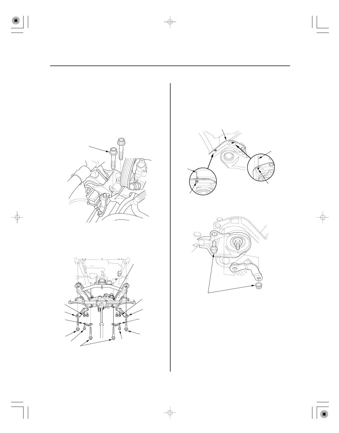
Engine Installation (cont’d)
10 x 1.25 mm
44 N·m
(4.5 kgf·m, 33 lbf·ft)
A
A
B
A
A
10 x 1.25 mm
38 N·m
(3.9 kgf·m, 28 lbf·ft)
B
14 x 1.5 mm
103 N·m
(10.5 kgf·m, 75.9 lbf·ft)
D
12 x 1.25 mm
117 N·m
(11.9 kgf·m, 86.1 lbf·ft)
B
E
E
B
E
E
C
D
C
12 x 1.25 mm
74 N·m
(7.5 kgf·m,
54 N·m)
A
EQS02BMDXSB0
5. Install the engine support hanger (AAR-T-12566) to
the vehicle, then attach the hook to the slotted hole
in the engine hanger balance bar. Tighten the wing
nut (F) by hand to lift and support the engine/
transmission assembly.
6. Install new mounting bolts into the upper half of
the engine mount bracket. Tighten the bolts to the
specified torque.
7.
lift to full height.
8. Using the subframe adapter (A) and a jack, raise
the front subframe up to the body.
9. Loosely install the new front subframe mounting
bolts (four) (B), the 12 x 1.25 mm bolts (six) (C) (D),
and the stiffeners (E).
10. Align all reference marks (A) on the front subframe
(B) with the body, then tighten the bolts on the front
subframe to the specified torque.
11. Install the bolt retainers on both ends of the
subframe.
12. Remove the jack and front subframe adapter.
Remove the chain hoist, then raise the vehicle on the