Honda Ridgeline. Manual - part 23


  Index      Honda     Honda Ridgeline - service repair manual 2006-2008 year


Search            


Content   ..  21  22  23  24   ..


Honda Ridgeline. Manual - part 23


01

02

03

SJC8A00A18223800000KAAT00

Special Tools Required

5-2

Engine Assembly

Engine Removal

A

B

• Front subframe adapter EQS02BMDXSB0
• Engine support hanger, A and Reds AAR-T-12566
• Engine hanger balance bar VSB02C000019
• Engine hanger adapter set VSB02C000024

These special tools are available through the Honda
Tool and Equipment program, 1-888-424-6857.

NOTE:

• Use fender covers to avoid damaging painted

surfaces.

• To avoid damage, unplug the wiring connectors

carefully while holding the connector portion.

• Mark all wiring and hoses to avoid misconnection.

Also, be sure that they do not contact other wiring,
hoses, or interfere with other parts.

1. Secure the hood in the wide open position (position

the support rod in the lower hole).

2. Relieve the fuel pressure (see page 11-286).

3. Drain the power steering system fluid, then plug

the fluid reservoir and return hose (see page 17-12).

4. Remove the bulkhead cover (see page 20-171).

5. Make sure you have the anti-theft codes for the

audio system and navigation system (if equipped).
Make sure the ignition switch is OFF.

6. Disconnect the negative cable from the battery,

then disconnect the positive cable.

7. Remove the battery.

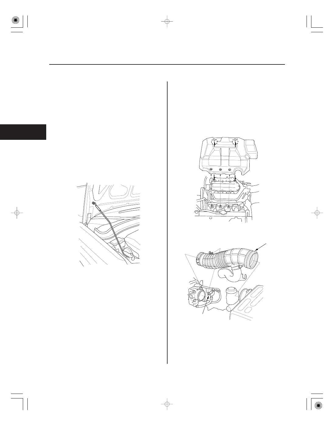
8. Remove the engine cover.

9. Disconnect the breather pipe (A), then remove the

air intake duct (B).

04

05

*01

07

5-3

A

B

A

C

A

B

A

B

A

B

C

D

10. Remove the harness clamps (A), then remove the

battery base (B).

11. Remove the ground cable (A), harness clamp (B)

and starter motor cable (C).

12. Remove the shift cable (see step 19 on page

14-219).

13. Remove the quick-connect fitting cover (A), then

disconnect the fuel feed hose (B) (see page 11-293).

14. Remove the transfer breather tube box (A) and

disconnect brake booster vacuum hose (B).

15. Disconnect the evaporative emission (EVAP)

canister hose (C), then remove the purge joint (D).

(cont’d)

08

09

10

11

5-4

Engine Assembly

Engine Removal (cont’d)

A

B

C

D

E

A

B

A

B

A

16. Remove the steering wheel (see page 17-21).

17. Remove the steering joint cover (A).

18. Make a reference mark (B) across the steering joint

and steering gearbox pinion shaft. Remove the
steering joint bolt (C), and loosen the steering joint
bolt (D), then disconnect the steering joint from the
steering gearbox pinion shaft (E).

19. Remove the alternator cable (A) from the under-

hood fuse/relay box.

20. Disconnect the harness connectors (B).

21. Remove the coolant reservoir from the bracket.

22. Remove the powertrain control module (PCM)

cover.

23. Remove the harness clamps (A), then disconnect

the two PCM connectors (B).

12

13

14

15

5-5

A

B

C

24. Remove the drive belt (see page 4-31).

25. Remove the power steering (P/S) pump inlet hose

(A) and P/S pump outlet hose (B) from the P/S
pump, then plug the P/S lines and P/S pump.

26. Remove the P/S hose clamp (C) from the cylinder

head cover.

27. Remove the radiator cap.

28. Raise the vehicle on the lift to full height.

29. Remove the front wheels.

30. Remove the splash shield.

31. Loosen the drain plug in the radiator, and drain the

engine coolant (see page 10-6).

32. Drain the automatic transmission fluid (ATF)

(see page 14-210).

33. Drain the engine oil (see page 8-6).

34. Remove the front subframe stiffener.

35. Remove exhaust pipe A.

(cont’d)


Content   ..  21  22  23  24   ..