Honda Ridgeline. Manual - part 22
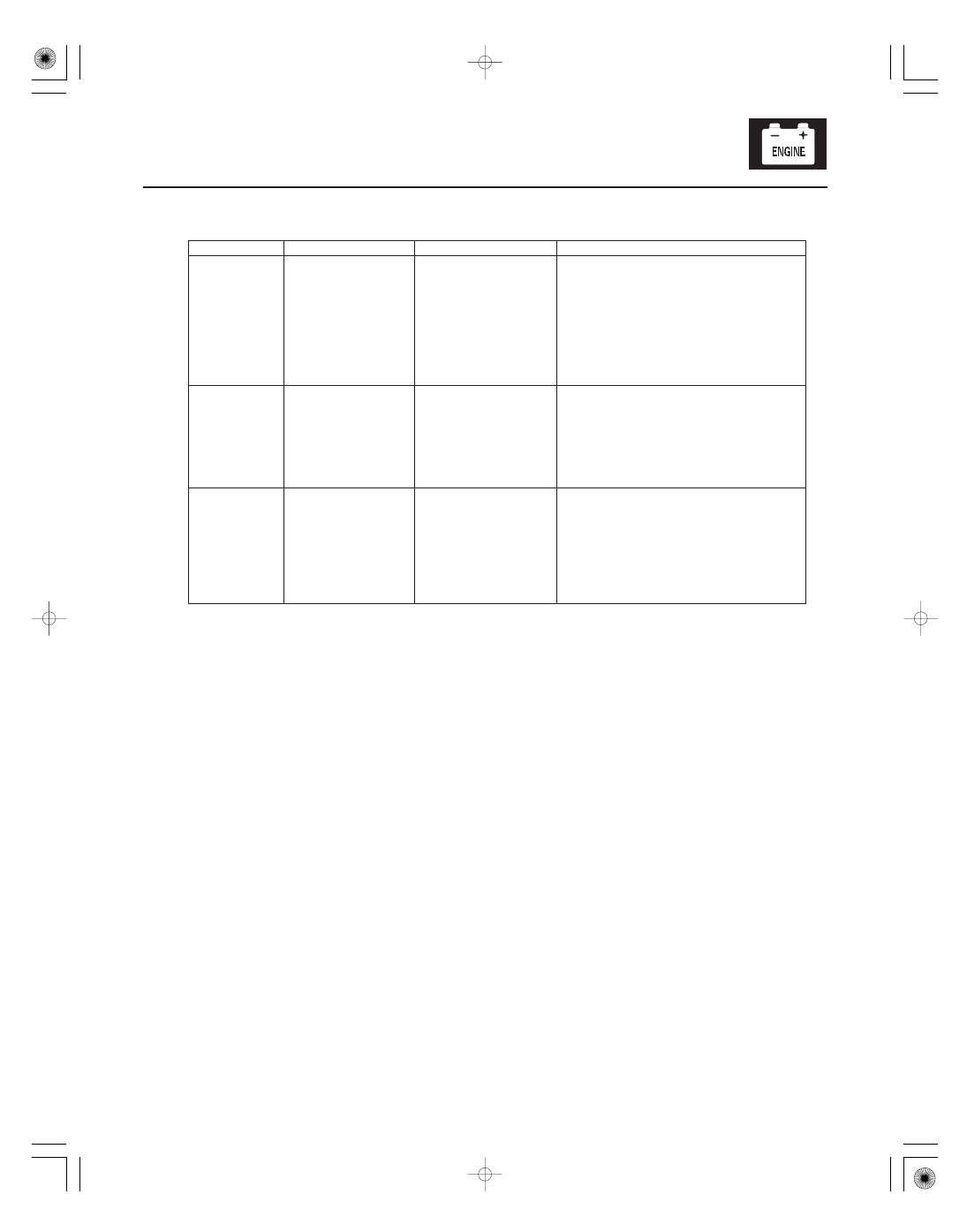
Signal to be tested
Parameter: Desired result
Test condition
Possible cause if result is not obtained
4-45
•
•
•
Resume
switch signal
Resume/accel switch
pressed and released
CRUISE CONTROL
RESUME SW should
indicate ON when the
resume/accel switch is
pressed and OFF when
the resume/accel
switch is released.
Faulty cruise control set/decel, resume/
accel, cancel switch
An open in the wire between the gauge
control module and the cruise control
set/decel, resume/accel, cancel switch
A wire shorted to ground between the
gauge control module and the cruise
control set/decel, resume/accel, cancel
switch
Cancel switch
signal
Cancel switch
pressed and released
CRUISE CONTROL
CANCEL SW should
indicate ON when the
cancel switch is
pressed and OFF when
the cancel switch is
released.
Faulty cruise control set/decel, resume/
accel, cancel switch
Cruise control
indicator
signal
Start the engine, turn
the cruise control
main switch on and
drive the vehicle
above 25 mph
(40 km/h). Set and
cancel the cruise
control.
CRUISE INDICATOR
should indicate ON
when the cruise control
is set and OFF when
the cruise control is
canceled.
Faulty gauge control module